
Page 510 - Subyek Teknik Mesin - Forsthoffers Best Practice Handbook for Rotating Machinery by William E Forsthoffer
P. 510
Pump Mechanical Seal Flush Best Practices Be st Practice 8.7
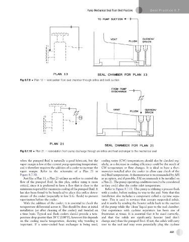
Fig 8.7.9 Plan 13 e recirculation from seal chamber through orifice and back suction
Fig 8.7.10 Plan 21 e recirculation from pump discharge through an orifice and heat exchanger to the mechanical seal
when the pumped fluid is naturally a good lubricant, but the cooling water (CW) temperatures should also be checked reg-
vapor margin is low at the current pump operating temperature, ularly, as a decrease in cooling efficiency could be the result of
and it therefore requires the addition of a cooler to increase the CW temperature or flow changes. It is ideal to have a ther-
vapor margin. Refer to the schematic of a Plan 21 in mometer installed after the cooler to allow easy check of the
Figure 8.7.10. seal fluid temperature. A thermometer is recommended by API
Just like a Plan 11, a Plan 21 utilizes an orifice to control the as an option, and if possible, FAI recommends it be installed on
flow of the pumped fluid. In this plan, orifice sizing is more a Plan 21. The pump operating conditions need to be considered
critical, since it is preferred to have a flow that is close to the as they could alter the cooler inlet temperature.
minimum required for maximum cooling of the pumped fluid. It Refer to Figure 8.7.11. This pump is utilizing a process flush
has also been found to be beneficial to place this orifice down- with a cooler, before making its way to the seal. Note that this
stream of the cooler (especially in low S.G. fluids) to prevent installation also includes a component called a cyclone sepa-
vaporization before the cooler. rator. This is used in services that contain suspended solids,
With the addition of the cooler, it is essential to check the and it works by sending the heavier solids back to the suction
temperature differential across it. This should be done at initial of the pump while the ‘clean’ liquid goes to the seal chamber.
installation (or after cleaning of the cooler) and trended on Our experience with cyclone separators has been one of
a time basis. Typical seal flush coolers should provide a tem- frustration at times. It is essential that it be sized correctly,
perature drop greater than 38 C (100 F), however this depends and that the solids are significantly heavier (and don’t
on the cooling media temperature, showing why trending is change size) than the pumped fluid. If not, the solids will carry
important. If a water-cooled heat exchanger is being used, over to the seal and may even potentially plug the cyclone
481