
Page 513 - Subyek Teknik Mesin - Forsthoffers Best Practice Handbook for Rotating Machinery by William E Forsthoffer
P. 513
Be st Practice 8 .7 Pump Mechanical Seal Flush Best Practices
a synthetic Plan 54 is usually provided with a pressure control thermosyphon). It is also essential in a Plan 23 to have a high
valve to automatically control the pressure. Note that pressure point vent and block valve installed, to allow for proper venting
control is adequate in most applications, however if the seal before pump start-up. Operators should be trained to un-
chamber pressure fluctuates during operation, a differential derstand the necessity of venting these systems.
pressure control should be considered. In monitoring this system, the temperature drop needs to be
Another consideration when making a decision on a synthetic checked across the cooler. Note that this temperature drop will
Plan 54 vs. a Process 54 or a Plan 32, is the potential addition of be less than in a Plan 21, due to the cooler not needing to provide
extra components. A synthetic Plan 54 will contain pump(s), the same amount of cooling. If the temperature drop across the
coolers, filters, and instrumentation. As everybody knows, the cooler is high (like a Plan 21 should be), it indicates that the
most reliable equipment has a balance of quality components and throat bushing clearance has increased and mixing of the pumped
is as simple as possible (fewest number of components). fluid and seal fluid is occurring. Typical temperature drop in
a Plan 23 can be anywhere from 7 Cto 10 C(20 Fto50 F).
This flush plan is most common in BFW applications, since
Considerations for closed loop system
water has poor lubricating qualities and needs to be as cool as
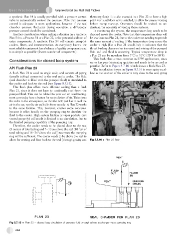
possible. Refer to Figure 8.7.16, which shows a flush Plan 23.
API Flush Plan 23 The installation shown in Figure 8.7.16 is once again excel-
A flush Plan 23 is used on single seals, and consists of piping lent as the location of the cooler is very close to the seal, giving
(usually tubing) connected to the seal and a cooler. The fluid
(seal chamber is filled with the pumped fluid) is circulated to
the cooler and back to the seal (see Figure 8.7.15).
This flush plan offers more efficient cooling than a flush
Plan 21, since it does not have to continually cool down the
pumped fluid. This can be related to your car air conditioning;
most cars today have a button for recirculation of air. This closes
the valve to the atmosphere, so that the A/C just has to cool the
air in the car, not the air pulled in from outside. A Plan 23 works
in the same fashion. This, however, creates some concerns,
because it relies heavily on the pumping ring to circulate the
fluid to the cooler. High system friction or vapor pockets (not
vented properly) will result in limited to no circulation, due to
the limited pumping capability of the pumping ring.
Therefore, the cooler needs to be placed close to the seal
(3 meters of total tubing and 7e10 cm above the seal [10 feet of
total tubing and 18e24" above the seal]) to ensure the pumping
ring will be sufficient. The cooler needs to be above the seal to
allow for venting and flow back to the seal (through gravity and Fig 8.7.16 Plan 23 flush
Fig 8.7.15 Plan 23 e closed loop circulation of process fluid through a heat exchanger via a pumping ring
484