
Page 509 - Subyek Teknik Mesin - Forsthoffers Best Practice Handbook for Rotating Machinery by William E Forsthoffer
P. 509
Be st Practice 8 .7 Pump Mechanical Seal Flush Best Practices
Fig 8.7.5 Plan 11 e recirculation from
discharge through orifice and to
mechanical seal
Single stage pumps – 1/8"
Multistage pumps – gang ori fi ces (series of orifices back to
back, sized by seal vendor)
Low S.G. fl uids may require higher fl ow rates to prevent fl ashing
(early vaporization) where a 3/16" orifice may be necessary
Fig 8.7.6 Orifice size guidelines e where used
throat bushing wears over time, the seal chamber pressure
will drop.
In a Plan 11 flush system, the main thing to monitor is the
temperature across the orifice. If this drops by more than 10%,
the orifice is most likely plugging up. If this is the first occur-
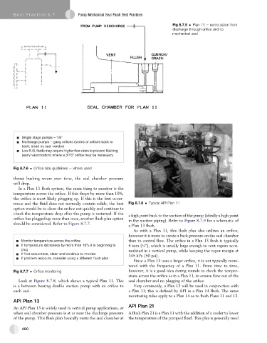
rence and the fluid does not normally contain solids, the best Fig 8.7.8 Typical API Plan 11
option would be to clean the orifice out quickly and continue to
check the temperature drop after the pump is restarted. If the a high point back to the suction of the pump (ideally a high point
orifice has plugged up more than once, another flush plan option in the suction piping). Refer to Figure 8.7.9 for a schematic of
should be considered. Refer to Figure 8.7.7.
a Plan 13 flush.
As with a Plan 11, this flush plan also utilizes an orifice,
however it is more to create a back pressure on the seal chamber
Monitor temperature across the ori fi ce than to control flow. The orifice in a Plan 13 flush is typically
If temperature decreases by more than 10% it is beginning to 6 mm (¼"), which is usually large enough to vent vapors accu-
plug mulated in a vertical pump, while keeping the vapor margin at
If fi rst occurrence, clean and continue to monitor 345 kPa (50 psi).
If problem reoccurs, consider using a different fl ush plan
Since a Plan 13 uses a larger orifice, it is not typically moni-
tored with the frequency of a Plan 11. From time to time,
Fig 8.7.7 Orifice monitoring however, it is a good idea during rounds to check the temper-
ature across the orifice as in a Plan 11, to ensure flow out of the
Look at Figure 8.7.8, which shows a typical Plan 11. This seal chamber and no plugging of the orifice.
is a between bearing double suction pump with an orifice to Very commonly, a Plan 13 will be used in conjunction with
each seal. a Plan 11; this is defined by API as a Plan 14 flush. The same
monitoring rules apply to a Plan 14 as to flush Plans 11 and 13.
API Plan 13
An API Plan 13 is widely used in vertical pump applications, or API Plan 21
when seal chamber pressure is at or near the discharge pressure A flush Plan 21 is a Plan 11 with the addition of a cooler to lower
of the pump. This flush plan basically vents the seal chamber at the temperature of the pumped fluid. This plan is generally used
480