
Page 514 - Subyek Teknik Mesin - Forsthoffers Best Practice Handbook for Rotating Machinery by William E Forsthoffer
P. 514
Pump Mechanical Seal Flush Best Practices Be st Practice 8.7
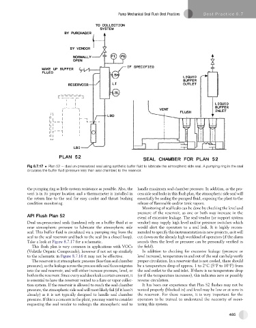
Fig 8.7.17 Plan 52 e dual un-pressurized seal using synthetic buffer fluid to lubricate the atmospheric side seal. A pumping ring in the seal
circulates the buffer fluid (pressure less than seal chamber) to the reservoir.
the pumping ring as little system resistance as possible. Also, the handle maximum seal chamber pressure. In addition, as the pro-
vent is in its proper location and a thermometer is installed in cess side seal leaks in this flush plan, the atmospheric side seal will
the return line to the seal for easy cooler and throat bushing essentially be sealing the pumped fluid, exposing the plant to the
condition monitoring. release of flammable and/or toxic vapors.
Monitoring of seal leaks can be done by checking the level and
pressure of the reservoir, as one or both may increase in the
API Flush Plan 52
event of excessive leakage. The seal vendor (or support system
Dual un-pressurized seals (tandem) rely on a buffer fluid at or vendor) may supply high level and/or pressure switches which
near atmospheric pressure to lubricate the atmospheric side would alert the operators to a seal leak. It is highly recom-
seal. This buffer fluid is circulated via a pumping ring from the mended to specify this instrumentation in new projects, as it will
seal to the seal reservoir and back to the seal (in a closed loop). cut down on the already high workload of operators (if the alarm
Take a look at Figure 8.7.17 for a schematic. sounds then the level or pressure can be personally verified in
This flush plan is very common in applications with VOCs the field).
(Volatile Organic Compounds), however if not set up similarly In addition to checking for excessive leakage (pressure or
to the schematic in Figure 8.7.16 it may not be effective. level increase), temperature in and out of the seal can help verify
The reservoir is atatmospheric pressure (less than seal chamber proper circulation. In a reservoir that is not cooled, there should
pressure), so the leakage across the process side seal faces migrates be a temperature drop of approx. 1 to 2 C(5 Fto10 F) from
into the seal reservoir, and will either increase pressure, level, or the seal outlet to the seal inlet. If there is no temperature drop
bothinthe reservoir.Since every sealdoesleaka certainamount, it (or if the temperature increases), this indicates zero or possibly
is essential to have the reservoir vented to a flare or vapor collec- reverse circulation.
tion system. If the reservoir is allowed to reach the seal chamber It has been our experience that Plan 52 flushes may not be
pressure, the atmospheric side seal will most likely fail (if it hasn’t vented properly (blocked in) and level may be low or at zero in
already) as it is not typically designed to handle seal chamber the reservoir. For these reasons, it is very important for the
pressure. If this is a concern in the plant, you may want to consider operators to be trained to understand the necessity of moni-
requesting the seal vendor to redesign the atmospheric seal to toring this system.
485