
Page 518 - Subyek Teknik Mesin - Forsthoffers Best Practice Handbook for Rotating Machinery by William E Forsthoffer
P. 518
Pump Mechanical Seal Flush Best Practices Be st Practice 8.8
The seal system
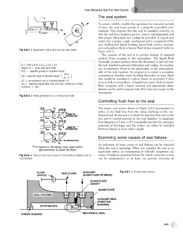
To ensure reliable, trouble-free operation for extended periods
of time, the seal must operate in a properly controlled envi-
ronment. This requires that the seal be installed correctly, so
that the seal faces maintain perfect contact and alignment, and
that proper lubrication and cooling be provided. A typical seal
system for a simple, single, mechanical seal is comprised of the
seal, stuffing box throat bushing, liquid flush system, auxiliary
seal and auxiliary flush or barrier fluid (when required) (refer to
Fig 8.8.4 Equivalent orifice flow across seal faces
Figure 8.8.7).
The purpose of the seal is to prevent leakage of pumped
product from escaping to the atmosphere. The liquid flush
(normally pumped product from the discharge) is injected into
Q = 500 S.G. Q, NJ Cp T the seal chamber to provide lubrication and cooling. An auxiliary
where: Q = heat load (BTU/HR) seal is sometimes fitted to the gland plate on the atmospheric
S.G. = specific gravity of injection liquid side of the seal chamber. Its purpose is to create a secondary
Cp = specific heat of injection liquid containment chamber, when handling flammable or toxic fluids
lb °F that would be considered a safety hazard to personnel if they
T = temperature rise of injection liquid (°F)
were to leak to atmosphere. A liquid (non-toxic) flush or barrier
Q INJ = injection liquid flow rate (G.P.M.). If flow is in LPM,
constant = 125. fluid, complete with a liquid reservoir and appropriate alarm
devices can be used to ensure toxic fluid does not escape to the
atmosphere.
Fig 8.8.5 Heat generated by a mechanical seal
Controlling flush flow to the seal
The simple seal system shown in Figure 8.8.8 incorporates an
orifice in the flush line from the pump discharge to the me-
chanical seal. Its purpose is to limit the injection flow rate to the
seal and to control pressure in the seal chamber. A minimum
bore diameter or 3 mm (1/8") is normally specified (to minimize
potential of blockage) and the orifice can either be installed
between flanges or in an orifice nipple.
Examining some causes of seal failures
An indication of some causes of seal failures can be obtained
while the seal is operating. When you consider the seal as an
equivalent orifice, an examination of ‘tell-tale’ symptoms can
Fig 8.8.6 Typical seal face pressure temperature relationship to causes of indicate potential failure for which corrective action
vaporization can be implemented or at least can provide direction of
Fig 8.8.7 Simple seal system
489