
Page 523 - Subyek Teknik Mesin - Forsthoffers Best Practice Handbook for Rotating Machinery by William E Forsthoffer
P. 523
Be st Practice 8 .11 Pump Mechanical Seal Flush Best Practices
B.P. 8.11. Supporting Material
Decreased Pump Flow:
Seal vendors design the seal balance ratio and select face ma- Increased P2
terials based on a parameter known as the PV to be able to Decreased P1
3
change the fluid to a vapor approximately / 4 of the way down Decreased S.G.
the seal faces (see Figure 8.11.1). Increased Pump Flow:
Decreased P2
Increased P1
Increased S.G.
Fig 8.11.3 Process effects on centrifugal pump flow
is designed to be at least 345 kpa (50 psi) or above the seal
fluid vapor pressure).
- The middle figure shows the desired design condition of
3
changing the fluid to a vapor approximately / 4 of the way
down the faces. This is the design basis since it is known that
fluid characteristics, temperature and/or pressure will
change during operation a certain amount. Excessive changes
in any or all of these parameters will lead to seal failure.
- The last mode shows the case of no vaporization and
apparent seal failure. In reality, this is not a failure but only
Fig 8.11.1 Mechanical seal primary face vaporization point
a seal fluid condition change that does not allow the seal fluid
to reach the fluid vapor pressure between the seal faces
before it exits the seal.
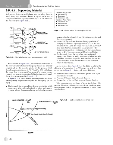
As can be seen in Figure 8.11.2, head required is a function of
the pressure differential across the pump flanges and inversely As can be seen from Figure 8.11.1, the ability to achieve the
3
proportional to the specific gravity of the pumped fluid. objective of vaporization / 4 or 75% down the seal faces (see
Therefore, process changes of P2, P1 and/or S.G. will change center case in Figure 8.11.1) depends on the following:
the pump flow in any centrifugal pump if a process control
system is not present or operational (failed or in manual mode). - Seal fluid characteristics e cleanliness, specific heat, vapor
pressure and viscosity
These facts are presented in Figure 8.11.3.
In Figure 8.11.1, three distinct operating modes are shown - Pressure of the seal fluid in the seal chamber
for the primary ring (on the left) and the mating ring (on the - Temperature of the seal fluid entering the seal chamber
right). What determines the condition of items listed above? The
- The top mode shows a condition of early vaporization which process. Therefore, effective mechanical seal condition moni-
can occur on light fluids, or hot fluids or where seal chamber toring requires that all seal process conditions, as noted above
pressure is lower than designed (note: seal chamber pressure are considered.
Fig 8.11.2 Head required by lower density fluid
494