
Page 524 - Subyek Teknik Mesin - Forsthoffers Best Practice Handbook for Rotating Machinery by William E Forsthoffer
P. 524
Pump Mechanical Seal Flush Best Practices Best Practice 8 .11
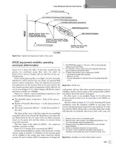
Fig 8.11.4 Typical centrifugal pump head vs. flow curve
EROE (equipment reliability operating
envelope) determination 1. The EROE flow range is + 10% and – 50% of the pump best
ef fi ciency point (BEP) fl ow
2. All ‘ bad actor ’ pumps (more than one component failure per
Figure 8.11.2 shows the effect of the head required by the
year) should be checked for EROE
process on centrifugal pump flow rate. As noted in
3. To determine that the pump is operating in EROE:
Figure 8.11.3, process changes will vary the flow of any cen- • Calculate the pump head required
trifugal pump. • Measure the fl ow
If the centrifugal pump flow is too high or too low, hydraulic • Plot the intersection of head and fl ow on the pump shop test
disturbances will be present that can change the pumped fluid curve
pressure and/or temperature. Since the majority of mechanical
seal applications use the pumped fluid in the seal chamber, the Fig 8.11.5 EROE facts
seal chamber pressure and/or temperature will be affected. As
can be seen in Figure 8.11.1, these changes will directly impact work permit, and any other plant required permission prior to
mechanical seal life and reliability. installing a suction pressure gauge as the pumped fluid could be
Figure 8.11.4 shows a typical centrifugal pump head vs. flow sour (H 2 S), flammable and/or carcinogenic.
curve with the following items noted: If a flow meter is not installed, Figure 8.11.6 defines the
options available to determine the pump flow so the EROE can
- The ‘desirable region’ of operation e heart of the curve or
EROE be obtained.
- Regions of hydraulic disturbances e on the upper portion of The flow values in Figure 8.11.6 can be determined by hand
the curve calculations using the equations available in any pump text
- The pump components affected e on the lower portion of (power equation and pump temperature rise equation). It can be
the curve seen that the EROE will provide a reasonable guide that usually
will eliminate the hydraulic disturbances that could cause seal
The ‘heart of the curve’ is the flow region for any centrifugal
pump that will be free of hydraulic disturbances and where the
seal fluid should be free of vapor if the seal fluid conditions
1. Measure motor amps and calculate power
stated on the pump and seal data sheets are present during 2. Record control valve position, valve differential pressure, fl uid
pump field operation. S.G. and calculate valve flow (pump flow)
This flow region is also called the EROE e the equipment 3. Measure pump pipe differential temperature and calculate
reliability operating envelope pump ef fi ciency
Figure 8.11.5 presents facts concerning the EROE. 4. Obtain an ultrasonic fl owmeter to measure fl ow
In many pump installations, neither a flow meter nor a suction 5. For items 1 and 3, locate the calculated value (power or
ef fi ciency) on the pump test curve to determine pump fl ow
pressure gauge is installed. A calibrated suction pressure gauge
can be installed in the suction pipe drain connection (always
present). Be sure to obtain a MOC (management of change) and Fig 8.11.6 Available pump flow determination options
495