
Page 507 - Subyek Teknik Mesin - Forsthoffers Best Practice Handbook for Rotating Machinery by William E Forsthoffer
P. 507
Be st Practice 8 .7 Pump Mechanical Seal Flush Best Practices
B.P. 8.6. Supporting Material
Install a pressure gauge in the seal chamber
Modify the seal flush line for installation of a pressure gauge
Pressure monitoring
Unless the plant assigned machinery specialist is ‘world class’ Fig 8.6.1 Seal chamber pressure monitoring guidelines for ‘bad
there are usually no pressure gauges in the flush line or seal actor’ seals
chamber. Our recommendations concerning seal chamber
pressure monitoring are presented in Figure 8.6.1. The mea- pressure is the value that was used in the calculation of the seal
sured seal chamber pressure must be compared to the seal PV. If the measured value does not agree with the data sheet,
vendor’s assumed value, which should be on the seal layout consult with operations first to see if process changes can be
drawing. If this value is not present, the seal vendor should be made. If process changes cannot be made, discuss this fact with
consulted. Note that the seal vendor assumed seal chamber the seal vendor representative.
Best Practice 8.7Practice 8.7Practice 8.7
Best
Best
Perform checks of all associated seal systems every time Lessons Learned
that the mechanical seal is replaced, to optimize safety and Failure to completely check the flush line, gland plate ports
MTBF. and all flush line components during a mechanical seal
Like bearings, the reliability of mechanical seals is a direct function replacement has resulted in low seal MTBFs and has ex-
of the reliability of all of its support system components. posed plant personnel and assets to damage.
To ensure that the root cause of a mechanical seal failure was not The root cause of many repeated mechanical seal failures has often
caused by a flush system component, all of the components in the flush
been eventually found in the flush system.
system should be checked each time a mechanical seal is replaced.
As a minimum, the following items should be checked:
Benchmarks
The flush line orifice for proper dimensions and cleanliness
This best practice has been used since 1990. Since that time, this
The flush line does not contain any restrictions (especially where
recommended maintenance procedure has resulted in optimum me-
flush line tubing is used and may be crimped)
chanical seal safety and reliability for all projects and field mechanical
All flush line components (cooler, strainer, cyclone separator, etc.)
seal reliability optimization audits.
The gland plate to ensure all ports are fully open and do not contain
any debris
Throat bushing clearances
B.P. 8.7. Supporting Material As is the case with hydrodynamic bearings, a mechanical seal
consists of a rotating part (shaft or thrust disc) and a stationary
part (shoes or brg housing). Contact between these two, just like
The importance of seal face lubrication rubbing your hands together, creates heat generated by friction.
Therefore, some type of lubricant (whether it be the pumped
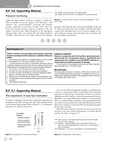
In order to understand the functions and design parameters of fluid or an external fluid) is required to keep a gap between the
mechanical seal flush systems one must first understand the two surfaces to keep them from contacting. This gap (created by
need for these flush systems. Refer to Figure 8.7.1, outlining the lubrication) results in a reduction of friction (or heat) generated
importance for seal face lubrication. between the two faces.
The fluid used to lubricate and take the heat away from the
seal faces must have certain characteristics to ensure optimal
seal face life. Refer to Figure 8.7.2.
Vapor pressure – the fluid should be at least 345 kPa (50 psi)
above its vapor pressure
Viscosity – typical limitations are no more than 100 Cst at
minimum pump temperature and no less than 1 Cst at highest
pump temperature
Cleanliness – fluid shall contain little to no suspended solids
Fig 8.7.1 Importance of seal face lubrication Fig 8.7.2 Sealing fluid characteristics
478