
Page 562 - Subyek Teknik Mesin - Forsthoffers Best Practice Handbook for Rotating Machinery by William E Forsthoffer
P. 562
The Post-Shipment Phase: Installation, Pre-Commissioning, Commissioning and Start-up Best Practices Best Practice 1 0.6
Pipe stress and soft foot exert failure producing forces on the
equipment casing from:
Top, side or bottom flanges (pipe loads)
Support feet (soft foot)
Fig 10.6.1 Pipe stress and soft foot
However, Figure 10.6.2 shows what the equipment designer
assumes in this regard.
Under the limit on external pipe force (on assembly dwg)
Fig 10.6.3 Single stage overhung pump (Courtesy of Union Pump Co).
Under the limit on external pipe moments (on assembly dwg)
All support feet are flat and in the same plane
Foundation under all support feet has been leveled (shimmed if
necessary with stainless steel shims)
All external pipe(s) and support feet are properly connected
In both figures, the process pipes are not connected. If, in
addition, both the pump and steam turbine were not coupled or
Fig 10.6.2 External force design assumptions bolted to their bases, what would cause the load (force) on the
bearings?
Hopefully your answer was the rotor. Let’s use the pump in
How pipe stress and soft foot can cause the following discussion (Figure 10.6.3). However, everything
component failure discussed will equally apply to the steam turbine or any other
type of equipment.
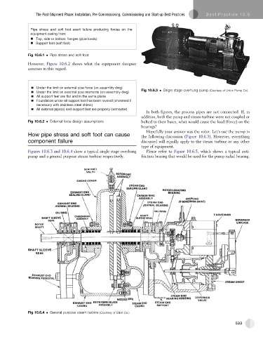
Figures 10.6.3 and 10.6.4 show a typical single stage overhung Please refer to Figure 10.6.5, which shows a typical anti-
pump and a general purpose steam turbine respectively. friction bearing that would be used for the pump radial bearing.
Fig 10.6.4 General purpose steam turbine (Courtesy of Elliott Co.)
533