
Page 563 - Subyek Teknik Mesin - Forsthoffers Best Practice Handbook for Rotating Machinery by William E Forsthoffer
P. 563
Be st Practice 1 0.6 The Post-Shipment Phase: Installation, Pre-Commissioning, Commissioning and Start-up Best Practices
‘B’ or ‘L’ - 10 life is defined as the life in hours that 9 out of 10
randomly selected bearings would exceed in a specific
application.
16700 ⎡⎤ 3
C
‘B’ or ‘L’ - 10 life = ⎢⎥
N ⎣⎦
F
Where: N = RPM
C = Load in lbs that will result in a bearing element life of
1,000,000 revolutions
F = Actual load in lbs
Fig 10.6.7 ‘B’ or ‘L’ - 10 life
Case 1 2 3
N (speed) 3600 rpm 3600 rpm 3600 rpm
C (bearing 3000 3000 3000
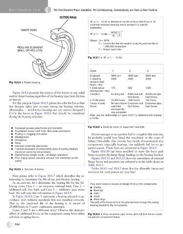
Fig 10.6.5 Radial bearing dynamic load
factor – lbs)
F (total actual 170 500 1000
bearing load – lbs)
Figure 10.6.6 presents the sources of the forces on any radial Condition As designed Additional soft Additional pipe
and/or thrust bearing regardless of the bearing type (anti-friction foot forces load forces
or sleeve). L-10 life years 25,495 hours 1002 hours 125 hours
For the pump in Figure 10.6.3, please describe the forces that Cause of early No early failure Excessive soft Excessive pipe
the designer takes into account during the bearing selection. failure specified foot forces load forces
(Remember e anti-friction bearings are not custom designed.) minimum life
Circle the forces in Figure 10.6.6 that should be considered was exceeded
during the bearing selection. Note: use the relationship in Figure 10.6.7 to determine the bearing
L-10 life.
Fig 10.6.8 External loads on equipment example
Increased process pipe forces and moments
Foundation forces (‘soft’ foot, differential settlement)
Fouling or plugging of impeller If your manager or an operator had to complete this exercise,
Misalignment he probably would have listed the ‘machinist’ as the cause of
Unbalance failure! Hopefully, this exercise has clearly demonstrated why
Rubs components, especially bearings, can suddenly fail for no ap-
Improper assembly clearances
Thermal expansion of components (loss of cooling medium, parent reason. These facts are presented in Figure 10.6.9.
excessive operating temperature) Figure 10.6.10 has been modified to show the force path
Radial forces (single volute – off design operation) from excessive discharge flange loadings to the bearing bracket.
Poor piping layouts (causing unequal flow distribution to the Figures 10.6.11 and 10.6.12 show the orientation of external
pump) flange forces and moments are referred to in the table shown in
Table 10.6.1.
Fig 10.6.6 Sources of forces Tables 10.6.1 and 10.6.2 show that the allowable forces and
moments for most pumps are very low!
Now please refer to Figure 10.6.7 which describes the re-
lationship to determine the life of any anti-friction bearing.
As an exercise, let’s determine the bearing life for the fol- They exert forces in excess of design limits on the components:
lowing cases; Case 1 e no excessive external load, Case 2 e
- Casing
additional soft foot load, and Case 3 e additional pipe stress - Bearings
load. We will note this information in Figure 10.6.8. - Rotor
In Figure 10.6.8, Case 1 represents a bearing selected in ac- - Seals
cordance with industry standards that was installed correctly. - Wear rings
That is, the predicted life of the bearing is in excess of The path of the forces is from the external force through the casing,
25,000 hours or 3 years’ continuous operation. bearing bracket to the components.
Cases 2 and 3 are a different story! Observe the dramatic
effect of additional forces on the equipment casing from either Fig 10.6.9 How excessive pipe stress and soft foot forces cause
soft foot or piping forces. equipment component failure
534