
Page 561 - Subyek Teknik Mesin - Forsthoffers Best Practice Handbook for Rotating Machinery by William E Forsthoffer
P. 561
Be st Practice 1 0.6 The Post-Shipment Phase: Installation, Pre-Commissioning, Commissioning and Start-up Best Practices
bolts and chocks should be greased for ease of operation once
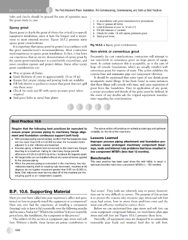
the grout starts to cure. 1. In accordance with grout manufacturers’ procedures
2. Wax or grease all forms
Epoxy grout 3. Limit thickness of pour to 10 cm (4")
4. Fill bolt sleeves or pockets
Epoxy grout is clearly the grout of choice for critical (un-spared) 5. Check for voids. Fill with epoxy pressure grout
equipment installation, since it lasts the longest and is imper- 6. Seal grout holes
vious to most external sources. Figure 10.5.2 presents some
epoxy grout considerations.
It is important that epoxy grout be poured in accordance with Fig 10.5.2 Epoxy grout considerations
the grout manufacturer’s recommendations. Most contractors Non-shrink or cementous grout
need experience in epoxy grout installation. In fact, it has been
our experience that an on-site demonstration of epoxy grout by Frequently for cost considerations, contractors will attempt to
the epoxy grout manufacturer is a worthwhile expenditure, and use non-shrink or cementous grout on large pieces of equip-
saves countless repours and project delays. Some other epoxy ment. In certain instances this is acceptable, as in the case of
grout considerations are: large oil console foundations, which are usually installed with
cementous grout for reasons of mass. This action solidifies the
- Wax or grease all forms console base and minimizes pipe and component vibration.
- Limit thickness of pour to approximately 10 cm (4 in) It should be mentioned that some types of non shrink grout
- Ensure that proper mixing and pouring tools are available incorporate metal filings. It has been found in some instances
- Fill bolt sleeves or pockets to ensure that grout does not spill that these filings will corrode with time, and cause separation of
into these areas grout from the foundation. Prior to application of any grout,
- Check for voids and fill with epoxy pressure grout when a proper procedure and details of the grout must be defined. In
required the event of any doubts ask the original equipment manufac-
- Seal grout holes in metal base plates turer regarding his considerations.
Best Practice 10.6Practice 10.6Practice 10.6Practice 10.6
Best
Best
Best
Require that the following best practices be executed to The above action will produce on-schedule start-ups and optimum
ensure proper process piping to machinery flange align- reliability for the life of the machinery.
ment and foundation continuous support (soft foot):
Lessons Learned
With process piping disconnected, confirm that the baseplate does
not rise more than 0.05 mm (0.002 in) when the foundation bolts Improper process piping attachment and foundation pro-
adjacent to a dial indicator are loosened. cedures cause prolonged machinery component (bear-
Process piping is floated (not connected) to the machinery flanges ings, seals and internal rub) problems that have resulted in
resulting in a maximum mating to machinery flange parallel low component MTBFs (less that 12 months).
difference of 0.25 mm (0.010 in) at four locations 90 degrees apart.
All flange bolts can be installed without any external forces applied Benchmarks
to the process piping.
This best practice has been used since the mid-1980s to result in
When the process piping is connected to the machinery, two dial
optimum installed machinery component MTBFs (> 100 months).
indicators reading shaft or coupling hub movement, mounted at 90
degrees, do not register movement greater than 0.05 mm (0.002 in).
Note: Dial indicators must be mounted off of the machine (on the
coupling guard or an independent support).
B.P. 10.6. Supporting Material ‘bad actors’. They both are relatively easy to prove; however,
they can be very difficult to correct. The purpose of this section
Have you ever been called into your supervisor’soffice and ques- is to present the reasons why excessive pipe stress and soft foot
tioned on how to properly install the equipment or a component? cause bad actors, how to prove these problems exist and the
Have you ever had the experience of installing a component most cost-effective method to correct them.
(bearing) only to have it fail repeatedly over the following months Before we can understand how pipe stress and soft foot can
and became a ‘bad actor’? What is the problem? Is it your assembly cause equipment component failures, we must know what pipe
procedures, the installation, the equipment or the process? stress and soft foot are! Figure 10.6.1 presents these facts.
The subject of this section is equipment pipe stress and soft Naturally, all equipment cases are designed to accommodate
foot. Without a doubt, these factors are prime contributors to reasonable pipe loads and minimal load due to soft foot.
532