
Page 559 - Subyek Teknik Mesin - Forsthoffers Best Practice Handbook for Rotating Machinery by William E Forsthoffer
P. 559
Be st Practice 1 0.4 The Post-Shipment Phase: Installation, Pre-Commissioning, Commissioning and Start-up Best Practices
crankcase and crossheads. After the foundation was set, with
the foundation bolts in place, it was discovered that the bolt
locations had moved from the original positions, and that the
crankcase could not be positioned over the foundation bolts.
The re-bar had interfered with the foundation bolts causing
them not to be correctly positioned. The result was complete
foundation rework to correctly position the foundation bolts
that resulted in a delay of one month to the construction
schedule. At that time the lost revenue was approximately
$1 MM per day.
One last word regarding foundation bolts. It is easy to mis-
locate the bolt locations relative to the machinery base plate
holes. Before bolt holes are randomly elongated to facilitate
misplaced location bolts, all facts should be discussed with both
Fig 10.4.1 Foundations the contractor and the vendor of the equipment. Irresponsible
action regarding elongation of bolt holes has caused machinery
provided. It is wise to epoxy-grout sole plates to facilitate easy problems. Fabricated foundation bolts on which welding is
removal and installation of equipment during maintenance. Sole used in the fabricated assembly must be stress relieved after
plates must be level in themselves and all other planes.
welding.
Foundation bolts
Leveling
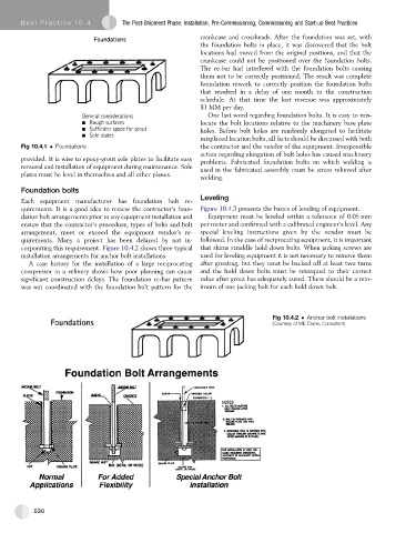
Each equipment manufacturer has foundation bolt re-
quirements. It is a good idea to review the contractor’s foun- Figure 10.4.3 presents the basics of leveling of equipment.
dation bolt arrangements prior to any equipment installation and Equipment must be leveled within a tolerance of 0.05 mm
ensure that the contractor’s procedure, types of bolts and bolt per meter and confirmed with a calibrated engineer’s level. Any
arrangement, meet or exceed the equipment vendor’s re- special leveling instructions given by the vendor must be
quirements. Many a project has been delayed by not in- followed. In the case of reciprocating equipment, it is important
corporating this requirement. Figure 10.4.2 shows three typical that shims straddle hold down bolts. When jacking screws are
installation arrangements for anchor bolt installations. used for leveling equipment it is not necessary to remove them
A case history for the installation of a large reciprocating after grouting, but they must be backed off at least two turns
compressor in a refinery shows how poor planning can cause and the hold down bolts must be retorqued to their correct
significant construction delays. The foundation re-bar pattern value after grout has adequately cured. There should be a min-
was not coordinated with the foundation bolt pattern for the imum of one jacking bolt for each hold down bolt.
Fig 10.4.2 Anchor bolt installations
(Courtesy of ME Crane, Consultant)
530