
Page 295 - T. Anderson-Fracture Mechanics - Fundamentals and Applns.-CRC (2005)
P. 295
1656_C006.fm Page 275 Monday, May 23, 2005 5:50 PM
Fracture Mechanisms in Nonmetals 275
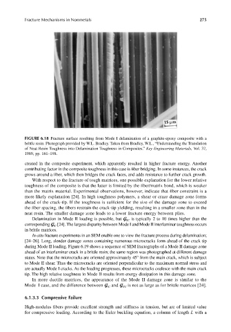
FIGURE 6.18 Fracture surface resulting from Mode I delamination of a graphite-epoxy composite with a
brittle resin. Photograph provided by W.L. Bradley. Taken from Bradley, W.L., “Understanding the Translation
of Neat Resin Toughness into Delamination Toughness in Composites.” Key Engineering Materials, Vol. 37,
1989, pp. 161–198.
created in the composite experiment, which apparently resulted in higher fracture energy. Another
contributing factor in the composite toughness in this case is fiber bridging. In some instances, the crack
grows around a fiber, which then bridges the crack faces, and adds resistance to further crack growth.
With respect to the fracture of tough matrices, one possible explanation for the lower relative
toughness of the composite is that the latter is limited by the fiber/matrix bond, which is weaker
than the matrix material. Experimental observations, however, indicate that fiber constraint is a
more likely explanation [24]. In high toughness polymers, a shear or craze damage zone forms
ahead of the crack-tip. If the toughness is sufficient for the size of the damage zone to exceed
the fiber spacing, the fibers restrain the crack-tip yielding, resulting in a smaller zone than in the
neat resin. The smaller damage zone leads to a lower fracture energy between plies.
Delamination in Mode II loading is possible, but G is typically 2 to 10 times higher than the
IIC
corresponding G [24]. The largest disparity between Mode I and Mode II interlaminar toughness occurs
IC
in brittle matrices.
In-situ fracture experiments in an SEM enable one to view the fracture process during delamination;
[24–26]. Long, slender damage zones containing numerous microcracks form ahead of the crack tip
during Mode II loading. Figure 6.19 shows a sequence of SEM fractographs of a Mode II damage zone
ahead of an interlaminar crack in a brittle resin; the same region was photographed at different damage
states. Note that the microcracks are oriented approximately 45° from the main crack, which is subject
to Mode II shear. Thus the microcracks are oriented perpendicular to the maximum normal stress and
are actually Mode I cracks. As the loading progresses, these microcracks coalesce with the main crack
tip. The high relative toughness in Mode II results from energy dissipation in this damage zone.
In more ductile matrices, the appearance of the Mode II damage zone is similar to the
Mode I case, and the difference between G and G is not as large as for brittle matrices [24].
IIC
IC
6.1.3.3 Compressive Failure
High-modulus fibers provide excellent strength and stiffness in tension, but are of limited value
for compressive loading. According to the Euler buckling equation, a column of length L with a