
Page 296 - T. Anderson-Fracture Mechanics - Fundamentals and Applns.-CRC (2005)
P. 296
1656_C006.fm Page 276 Monday, May 23, 2005 5:50 PM
276 Fracture Mechanics: Fundamentals and Applications
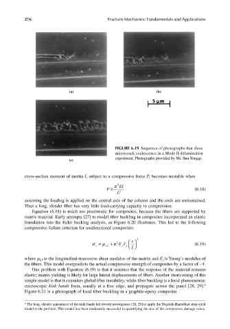
(a) (b)
FIGURE 6.19 Sequence of photographs that show
microcrack coalescence in a Mode II delamination
experiment. Photographs provided by Mr. Sun Yongqi.
(c)
cross-section moment of inertia I, subject to a compressive force P, becomes unstable when
π 2 EI
P ≥ (6.18)
L 2
assuming the loading is applied on the central axis of the column and the ends are unrestrained.
Thus a long, slender fiber has very little load-carrying capacity in compression.
Equation (6.18) is much too pessimistic for composites, because the fibers are supported by
matrix material. Early attempts [27] to model fiber buckling in composites incorporated an elastic
foundation into the Euler bucking analysis, as Figure 6.20 illustrates. This led to the following
compressive failure criterion for unidirectional composites:
r
σ c µ = L T π + 2 EV f L 2 (6.19)
f
where µ is the longitudinal-transverse shear modulus of the matrix and E is Young’s modulus of
f
LT
the fibers. This model overpredicts the actual compressive strength of composites by a factor of ∼4.
One problem with Equation (6.19) is that it assumes that the response of the material remains
elastic; matrix yielding is likely for large lateral displacements of fibers. Another shortcoming of this
simple model is that it considers global fiber instability, while fiber buckling is a local phenomenon;
microscopic kink bands form, usually at a free edge, and propagate across the panel [28, 29]. 6
Figure 6.21 is a photograph of local fiber buckling in a graphite-epoxy composite.
6 The long, slender appearance of the kink bands led several investigators [28, 29] to apply the Dugdale-Barenblatt strip-yield
model to the problem. This model has been moderately successful in quantifying the size of the compressive damage zones.