
Page 321 - T. Anderson-Fracture Mechanics - Fundamentals and Applns.-CRC (2005)
P. 321
1656_C007.fm Page 301 Monday, May 23, 2005 5:54 PM
Fracture Toughness Testing of Metals 301
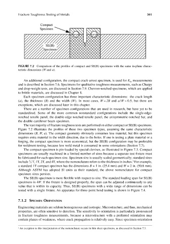
FIGURE 7.2 Comparison of the profiles of compact and SE(B) specimens with the same in-plane charac-
teristic dimensions (W and a).
An additional configuration, the compact crack-arrest specimen, is used for K measurements
Ia
and is described in Section 7.6. Specimens for qualitative toughness measurements, such as Charpy
and drop-weight tests, are discussed in Section 7.9. Chevron-notched specimens, which are applied
to brittle materials, are discussed in Chapter 8.
Each specimen configuration has three important characteristic dimensions: the crack length
(a), the thickness (B) and the width (W). In most cases, W = 2B and a/W ≈ 0.5, but there are
exceptions, which are discussed later in this chapter.
There are a number of specimen configurations that are used in research, but have yet to be
standardized. Some of the more common nonstandard configurations include the single-edge-
notched tensile panel, the double-edge-notched tensile panel, the axisymmetric-notched bar, and
the double cantilever beam specimen.
The vast majority of fracture toughness tests are performed on either compact or SE(B) specimens.
Figure 7.2 illustrates the profiles of these two specimen types, assuming the same characteristic
dimensions (B, W, a). The compact geometry obviously consumes less material, but this specimen
requires extra material in the width direction, due to the holes. If one is testing a plate material or a
forging, the compact specimen is more economical, but the SE(B) configuration may be preferable
for weldment testing, because less weld metal is consumed in some orientations (Section 7.7).
The compact specimen is pin-loaded by special clevises, as illustrated in Figure 7.3. Compact
specimens are usually machined in a limited number of sizes because a separate test fixture must
be fabricated for each specimen size. Specimen size is usually scaled geometrically; standard sizes
1
include 1 2 T, 1T, 2T, and 4T, where the nomenclature refers to the thickness in inches. For example,
a standard 1T compact specimen has the dimensions B = 1 in. (25.4 mm) and W = 2 in. (50.8 mm).
Although ASTM has adopted SI units as their standard, the above nomenclature for compact
specimen sizes persists.
The SE(B) specimen is more flexible with respect to size. The standard loading span for SE(B)
specimens is 4W. If the fixture is designed properly, the span can be adjusted continuously to any
value that is within its capacity. Thus, SE(B) specimens with a wide range of dimensions can be
tested with a single fixture. An apparatus for three-point bend testing is shown in Figure 7.4.
7.1.2 SPECIMEN ORIENTATION
Engineering materials are seldom homogeneous and isotropic. Microstructure, and thus, mechanical
properties, are often sensitive to direction. The sensitivity to orientation is particularly pronounced
in fracture toughness measurements, because a microstructure with a preferred orientation may
contain planes of weakness, where crack propagation is relatively easy. Since specimen orientation
1 An exception to this interpretation of the nomenclature occurs in thin sheet specimens, as discussed in Section 7.3.