
Page 326 - T. Anderson-Fracture Mechanics - Fundamentals and Applns.-CRC (2005)
P. 326
1656_C007.fm Page 306 Monday, May 23, 2005 5:54 PM
306 Fracture Mechanics: Fundamentals and Applications
FIGURE 7.9 Schematic of a linear variable differential transformer (LVDT). Electric current in the first coil
induces a magnetic field, which produces a voltage in the second coil. Displacement of the central core causes
a variation in the output voltage.
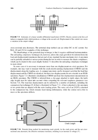
cross-sectional area decreases. The potential drop method can use either DC or AC current. See
Refs. [2] and [3] for examples of this technique.
The disadvantage of the potential drop technique is that it requires additional instrumentation.
The unloading compliance technique [4], however, allows the crack growth to be inferred from the
load and displacement transducers that are part of any standard fracture mechanics test. A specimen
can be partially unloaded at various points during the test in order to measure the elastic compliance,
which can be related to the crack length. Section 7.4 describes the unloading compliance technique
in more detail.
In some cases it is necessary to measure more than one displacement on a test specimen. For
example, one may want to measure both the crack-mouth-opening displacement (CMOD) and the
displacement along the loading axis. A compact specimen can be designed such that the load line
displacement and the CMOD are identical, but these two displacements do not coincide in an SE(B)
specimen. Figure 7.11 illustrates simultaneous CMOD and load line displacement measurement in
an SE(B) specimen. The CMOD is inferred from a clip gage attached to knife edges; the knife
edge height must be taken into account when computing the relevant toughness parameter (see
Section 7.5). The load-line displacement can be inferred by a number of methods, including the
comparison bar technique [5, 6] that is illustrated in Figure 7.11. A bar is attached to the specimen
at two points that are aligned with the outer loading points. The outer coil of an LVDT is attached
to the comparison bar, which remains fixed during deformation, while the central rod is free to
move as the specimen deflects.
FIGURE 7.10 Potential drop method for monitoring crack growth. As the crack grows and the net cross-
sectional area decreases, the effective resistance increases, resulting in an increase in voltage (V ).