
Page 323 - T. Anderson-Fracture Mechanics - Fundamentals and Applns.-CRC (2005)
P. 323
1656_C007.fm Page 303 Monday, May 23, 2005 5:54 PM
Fracture Toughness Testing of Metals 303
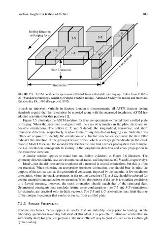
FIGURE 7.5 ASTM notation for specimens extracted from rolled plate and forgings. Taken from E 1823-
96, ‘‘Standard Terminology Relating to Fatigue Fracture Testing.’’ American Society for Testing and Materials,
Philadelphia, PA, 1996 (Reapproved 2002).
is such an important variable in fracture toughness measurements, all ASTM fracture testing
standards require that the orientation be reported along with the measured toughness; ASTM has
adopted a notation for this purpose [1].
Figure 7.5 illustrates the ASTM notation for fracture specimens extracted from a rolled plate
or forging. When the specimen is aligned with the axes of symmetry in the plate, there are six
possible orientations. The letters L, T, and S denote the longitudinal, transverse, and short
transverse directions, respectively, relative to the rolling direction or forging axis. Note that two
letters are required to identify the orientation of a fracture mechanics specimen; the first letter
indicates the direction of the principal tensile stress, which is always perpendicular to the crack
plane in Mode I tests, and the second letter denotes the direction of crack propagation. For example,
the L-T orientation corresponds to loading in the longitudinal direction and crack propagation in
the transverse direction.
A similar notation applies to round bars and hollow cylinders, as Figure 7.6 illustrates. The
symmetry directions in this case are circumferential, radial, and longitudinal (C, R, and L, respectively).
Ideally, one should measure the toughness of a material in several orientations, but this is often
not practical. When choosing an appropriate specimen orientation, one should bear in mind the
purpose of the test, as well as the geometrical constraints imposed by the material. A low toughness
orientation, where the crack propagates in the rolling direction (T-L or S-L), should be adopted for
general material characterization or screening. When the purpose of the test is to simulate conditions
in a flawed structure, however, the crack orientation should match that of the structural flaw.
Geometrical constraints may preclude testing some configurations; the S-L and S-T orientations,
for example, are practical only in thick sections. The T-S and L-S orientations may limit the size
of the compact specimen that can be extracted from a rolled plate.
7.1.3 FATIGUE PRECRACKING
Fracture mechanics theory applies to cracks that are infinitely sharp prior to loading. While
laboratory specimens invariably fall short of this ideal, it is possible to introduce cracks that are
sufficiently sharp for practical purposes. The most efficient way to produce such a crack is through
cyclic loading.