
Page 325 - T. Anderson-Fracture Mechanics - Fundamentals and Applns.-CRC (2005)
P. 325
1656_C007.fm Page 305 Monday, May 23, 2005 5:54 PM
Fracture Toughness Testing of Metals 305
Each of the various fracture testing standards contains restrictions on fatigue loads, which are
designed to satisfy the above requirements. The precise guidelines depend on the nature of the test.
In K tests, for example, the maximum K during fatigue loading must be no greater than a particular
Ic
fraction of K . In J and CTOD tests, where the test specimen is typically fully plastic at failure,
Ic
the maximum fatigue load is defined as a fraction of the load at ligament yielding. Of course one
can always perform fatigue precracking well below the allowable loads in order to gain additional
assurance of the validity of the results, but the time required to produce the crack (i.e., the number
of cycles) increases rapidly with decreasing fatigue loads.
7.1.4 INSTRUMENTATION
At a minimum, the applied load and a characteristic displacement on the specimen must be measured
during a fracture toughness test. Additional instrumentation is applied to some specimens in order
to monitor the crack growth or to measure more than one displacement.
Measuring load during a conventional fracture toughness test is relatively straightforward, since
nearly all test machines are equipped with load cells. The most common displacement transducer
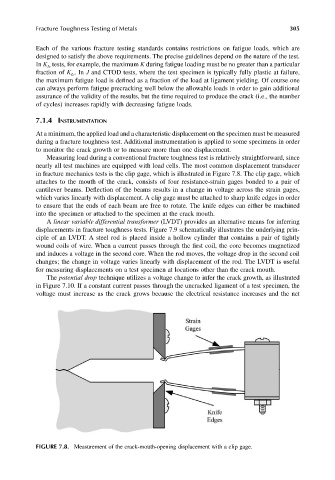
in fracture mechanics tests is the clip gage, which is illustrated in Figure 7.8. The clip gage, which
attaches to the mouth of the crack, consists of four resistance-strain gages bonded to a pair of
cantilever beams. Deflection of the beams results in a change in voltage across the strain gages,
which varies linearly with displacement. A clip gage must be attached to sharp knife edges in order
to ensure that the ends of each beam are free to rotate. The knife edges can either be machined
into the specimen or attached to the specimen at the crack mouth.
A linear variable differential transformer (LVDT) provides an alternative means for inferring
displacements in fracture toughness tests. Figure 7.9 schematically illustrates the underlying prin-
ciple of an LVDT. A steel rod is placed inside a hollow cylinder that contains a pair of tightly
wound coils of wire. When a current passes through the first coil, the core becomes magnetized
and induces a voltage in the second core. When the rod moves, the voltage drop in the second coil
changes; the change in voltage varies linearly with displacement of the rod. The LVDT is useful
for measuring displacements on a test specimen at locations other than the crack mouth.
The potential drop technique utilizes a voltage change to infer the crack growth, as illustrated
in Figure 7.10. If a constant current passes through the uncracked ligament of a test specimen, the
voltage must increase as the crack grows because the electrical resistance increases and the net
FIGURE 7.8. Measurement of the crack-mouth-opening displacement with a clip gage.