
Page 324 - T. Anderson-Fracture Mechanics - Fundamentals and Applns.-CRC (2005)
P. 324
1656_C007.fm Page 304 Monday, May 23, 2005 5:54 PM
304 Fracture Mechanics: Fundamentals and Applications
FIGURE 7.6 ASTM notation for specimens extracted from disks and hollow cylinders. Taken from E 1823-
96, ‘‘Standard Terminology Relating to Fatigue Fracture Testing.’’ American Society for Testing and Materials,
Philadelphia, PA, 1996 (Reapproved 2002).
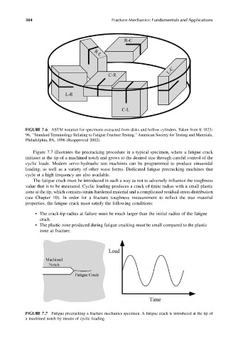
Figure 7.7 illustrates the precracking procedure in a typical specimen, where a fatigue crack
initiates at the tip of a machined notch and grows to the desired size through careful control of the
cyclic loads. Modern servo-hydraulic test machines can be programmed to produce sinusoidal
loading, as well as a variety of other wave forms. Dedicated fatigue precracking machines that
cycle at a high frequency are also available.
The fatigue crack must be introduced in such a way as not to adversely influence the toughness
value that is to be measured. Cyclic loading produces a crack of finite radius with a small plastic
zone at the tip, which contains strain-hardened material and a complicated residual stress distribution
(see Chapter 10). In order for a fracture toughness measurement to reflect the true material
properties, the fatigue crack must satisfy the following conditions:
• The crack-tip radius at failure must be much larger than the initial radius of the fatigue
crack.
• The plastic zone produced during fatigue cracking must be small compared to the plastic
zone at fracture.
FIGURE 7.7 Fatigue precracking a fracture mechanics specimen. A fatigue crack is introduced at the tip of
a machined notch by means of cyclic loading.