
Page 401 - T. Anderson-Fracture Mechanics - Fundamentals and Applns.-CRC (2005)
P. 401
1656_C008.fm Page 381 Monday, May 23, 2005 5:59 PM
Fracture Testing of Nonmetals 381
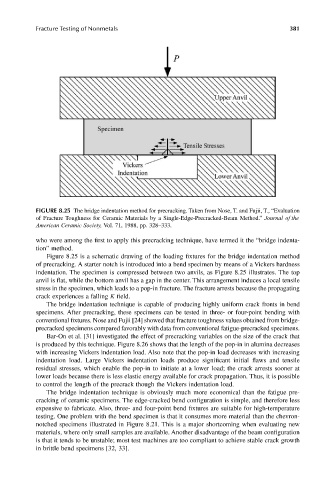
FIGURE 8.25 The bridge indentation method for precracking. Taken from Nose, T. and Fujii, T., “Evaluation
of Fracture Toughness for Ceramic Materials by a Single-Edge-Precracked-Beam Method.” Journal of the
American Ceramic Society, Vol. 71, 1988, pp. 328–333.
who were among the first to apply this precracking technique, have termed it the “bridge indenta-
tion” method.
Figure 8.25 is a schematic drawing of the loading fixtures for the bridge indentation method
of precracking. A starter notch is introduced into a bend specimen by means of a Vickers hardness
indentation. The specimen is compressed between two anvils, as Figure 8.25 illustrates. The top
anvil is flat, while the bottom anvil has a gap in the center. This arrangement induces a local tensile
stress in the specimen, which leads to a pop-in fracture. The fracture arrests because the propagating
crack experiences a falling K field.
The bridge indentation technique is capable of producing highly uniform crack fronts in bend
specimens. After precracking, these specimens can be tested in three- or four-point bending with
conventional fixtures. Nose and Fujii [24] showed that fracture toughness values obtained from bridge-
precracked specimens compared favorably with data from conventional fatigue-precracked specimens.
Bar-On et al. [31] investigated the effect of precracking variables on the size of the crack that
is produced by this technique. Figure 8.26 shows that the length of the pop-in in alumina decreases
with increasing Vickers indentation load. Also note that the pop-in load decreases with increasing
indentation load. Large Vickers indentation loads produce significant initial flaws and tensile
residual stresses, which enable the pop-in to initiate at a lower load; the crack arrests sooner at
lower loads because there is less elastic energy available for crack propagation. Thus, it is possible
to control the length of the precrack though the Vickers indentation load.
The bridge indentation technique is obviously much more economical than the fatigue pre-
cracking of ceramic specimens. The edge-cracked bend configuration is simple, and therefore less
expensive to fabricate. Also, three- and four-point bend fixtures are suitable for high-temperature
testing. One problem with the bend specimen is that it consumes more material than the chevron-
notched specimens illustrated in Figure 8.21. This is a major shortcoming when evaluating new
materials, where only small samples are available. Another disadvantage of the beam configuration
is that it tends to be unstable; most test machines are too compliant to achieve stable crack growth
in brittle bend specimens [32, 33].