
Page 400 - T. Anderson-Fracture Mechanics - Fundamentals and Applns.-CRC (2005)
P. 400
1656_C008.fm Page 380 Monday, May 23, 2005 5:59 PM
380 Fracture Mechanics: Fundamentals and Applications
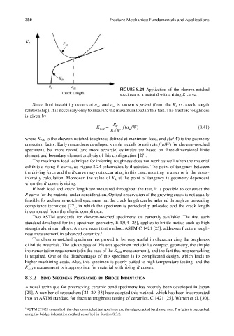
FIGURE 8.24 Application of the chevron-notched
specimen to a material with a rising R curve.
Since final instability occurs at a , and a is known a priori (from the K vs. crack length
m
m
I
relationship), it is necessary only to measure the maximum load in this test. The fracture toughness
is given by
P
K IvM = BW fa W) (8.41)
M
(
/
m
where K is the chevron-notched toughness defined at maximum load, and f(a/W) is the geometry
IvM
correction factor. Early researchers developed simple models to estimate f(a/W) for chevron-notched
specimens, but more recent (and more accurate) estimates are based on three-dimensional finite
element and boundary element analysis of this configuration [27].
The maximum load technique for inferring toughness does not work as well when the material
exhibits a rising R curve, as Figure 8.24 schematically illustrates. The point of tangency between
the driving force and the R curve may not occur at a in this case, resulting in an error in the stress-
m
intensity calculation. Moreover, the value of K at the point of tangency is geometry dependent
R
when the R curve is rising.
If both load and crack length are measured throughout the test, it is possible to construct the
R curve for the material under consideration. Optical observation of the growing crack is not usually
feasible for a chevron-notched specimen, but the crack length can be inferred through an unloading
compliance technique [22], in which the specimen is periodically unloaded and the crack length
is computed from the elastic compliance.
Two ASTM standards for chevron-notched specimens are currently available. The first such
standard developed for this specimen geometry, E 1304 [25], applies to brittle metals such as high
strength aluminum alloys. A more recent test method, ASTM C 1421 [25], addresses fracture tough-
ness measurement in advanced ceramics. 3
The chevron-notched specimen has proved to be very useful in characterizing the toughness
of brittle materials. The advantages of this test specimen include its compact geometry, the simple
instrumentation requirements (in the case of the K IvM measurement), and the fact that no precracking
is required. One of the disadvantages of this specimen is its complicated design, which leads to
higher machining costs. Also, this specimen is poorly suited to high-temperature testing, and the
K IvM measurement is inappropriate for material with rising R curves.
8.3.2 BEND SPECIMENS PRECRACKED BY BRIDGE INDENTATION
A novel technique for precracking ceramic bend specimens has recently been developed in Japan
[29]. A number of researchers [24, 29–33] have adopted this method, which has been incorporated
into an ASTM standard for fracture toughness testing of ceramics, C 1421 [25]. Warren et al. [30],
3 ASTM C 1421 covers both the chevron-notched test specimen and the edge-cracked bend specimen. The latter is precracked
using the bridge indentation method described in Section 8.3.2.