Page 395 - T. Anderson-Fracture Mechanics - Fundamentals and Applns.-CRC (2005)
P. 395

1656_C008.fm  Page 375  Monday, May 23, 2005  5:59 PM


                       Fracture Testing of Nonmetals                                               375


                                                             (a)


                                                             (b)

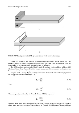
                       FIGURE 8.17 Loading fixtures for DCB specimens: (a) end blocks and (b) piano hinges.


                          Figure 8.17 illustrates two common fixtures that facilitate loading the DCB specimen. The
                       blocks or hinges are normally adhesively bonded to the specimen. These fixtures must allow the
                       free rotation of the specimen ends with a minimum of stiffening.
                          The DCB specimen can be tested in Mode I, Mode II, or mixed-mode conditions, as Figure 8.18
                       illustrates. Recall from Chapter 2 that the energy release rate of this specimen configuration can
                       be inferred from the beam theory.
                          For pure Mode I loading (Figure 8.18(a)), elastic beam theory leads to the following expression
                       for energy release rate (see Example 2.2):
                                                              Pa
                                                               22
                                                          G =  BEI                               (8.36)
                                                               I
                                                           I
                       where

                                                              2 Pa 3
                                                          EI =  I                                (8.37)
                                                               3∆ I

                       The corresponding relationship for Mode II (Figure 8.18(b)) is given by

                                                                22
                                                              3 Pa
                                                          G =   II                               (8.38)
                                                           II
                                                              4 BEI
                       assuming linear beam theory. Mixed-loading conditions can be achieved by unequal tensile loading
                       of the upper and lower portions of the specimens, as Figure 8.18(c) illustrates. The applied loads
   390   391   392   393   394   395   396   397   398   399   400