
Page 394 - T. Anderson-Fracture Mechanics - Fundamentals and Applns.-CRC (2005)
P. 394
1656_C008.fm Page 374 Monday, May 23, 2005 5:59 PM
374 Fracture Mechanics: Fundamentals and Applications
(a)
(b)
(c)
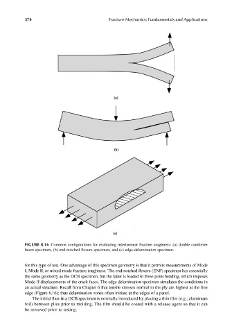
FIGURE 8.16 Common configurations for evaluating interlaminar fracture toughness: (a) double cantilever
beam specimen, (b) end-notched flexure specimen, and (c) edge-delamination specimen.
for this type of test. One advantage of this specimen geometry is that it permits measurements of Mode
I, Mode II, or mixed mode fracture toughness. The end-notched flexure (ENF) specimen has essentially
the same geometry as the DCB specimen, but the latter is loaded in three-point bending, which imposes
Mode II displacements of the crack faces. The edge delamination specimen simulates the conditions in
an actual structure. Recall from Chapter 6 that tensile stresses normal to the ply are highest at the free
edge (Figure 6.16); thus delamination zones often initiate at the edges of a panel.
The initial flaw in a DCB specimen is normally introduced by placing a thin film (e.g., aluminum
foil) between plies prior to molding. The film should be coated with a release agent so that it can
be removed prior to testing.