
Page 408 - T. Anderson-Fracture Mechanics - Fundamentals and Applns.-CRC (2005)
P. 408
1656_C009.fm Page 388 Monday, May 23, 2005 3:58 PM
388 Fracture Mechanics: Fundamentals and Applications
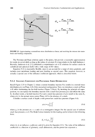
FIGURE 9.3 Approximating a nonuniform stress distribution as linear, and resolving the stresses into mem-
brane and bending components.
The Newman and Raju solutions apply to flat plates, but provide a reasonable approximation
for cracks in curved shells as long as the radius of curvature R is large relative to the shell thickness t.
Recently, Anderson et al. [11] published a comprehensive set of K solutions for surface cracks in
cylindrical and spherical shells with a wide range of R/t values.
Equation (9.2) is reasonably flexible, since it can account for a range of stress gradients, and
includes pure membrane loading and pure bending as special cases. This equation, however, is
actually a special case of the influence coefficient approach, which is described below.
9.1.2 INFLUENCE COEFFICIENTS FOR POLYNOMIAL STRESS DISTRIBUTIONS
Recall Figure 2.25 in Chapter 2, where a remote boundary traction P(x) results in a normal stress
distribution p(x) on Plane A-B of this uncracked configuration. Next, we introduce a crack on Plane
A-B while maintaining the far-field traction (Figure 2.26(a)). By invoking the principle of super-
position, we can replace the boundary traction with a crack-face pressure p(x) and obtain the same
K . In other words, a far-field traction P(x) and a crack-face pressure of p(x) result in the same K ,
I
I
where p(x) is the normal stress across Plane A-B in the absence of a crack.
Consider a surface crack of depth a with power-law crack-face pressure (Figure 9.4):
x
px() = p n a n (9.4)
where p is the pressure at x = a and n is a nonnegative integer. For the special case of uniform
n
crack-face pressure, n = 0. The Mode I stress intensity for this loading can be written in the following
form:
π a
K I G = n p n Q (9.5)
where G is an influence coefficient, and Q is given by Equation (9.3). The value of the influence
n
coefficient is a function of geometry, crack dimensions, and the power-law exponent n.