
Page 407 - T. Anderson-Fracture Mechanics - Fundamentals and Applns.-CRC (2005)
P. 407
1656_C009.fm Page 387 Monday, May 23, 2005 3:58 PM
Application to Structures 387
9.1.1 K FOR PART-THROUGH CRACKS
I
Laboratory fracture toughness specimens usually contain idealized cracks, but naturally occurring
flaws in structures are under no obligation to live up to these ideals. Structural flaws are typically
irregular in shape and are part-way through the section thickness. Moreover, severe stress gradients
often arise in practical situations, while laboratory specimens experience relatively simple loading.
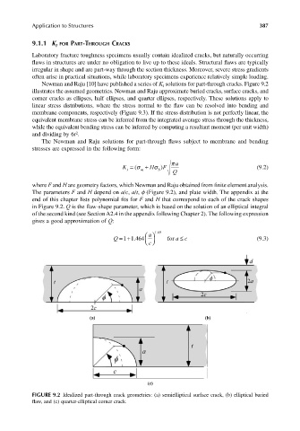
Newman and Raju [10] have published a series of K solutions for part-through cracks. Figure 9.2
I
illustrates the assumed geometries. Newman and Raju approximate buried cracks, surface cracks, and
corner cracks as ellipses, half ellipses, and quarter ellipses, respectively. These solutions apply to
linear stress distributions, where the stress normal to the flaw can be resolved into bending and
membrane components, respectively (Figure 9.3). If the stress distribution is not perfectly linear, the
equivalent membrane stress can be inferred from the integrated average stress through the thickness,
while the equivalent bending stress can be inferred by computing a resultant moment (per unit width)
2
and dividing by 6t .
The Newman and Raju solutions for part-through flaws subject to membrane and bending
stresses are expressed in the following form:
π a
K I m H = σ b ) F + (σ Q (9.2)
where F and H are geometry factors, which Newman and Raju obtained from finite element analysis.
The parameters F and H depend on a/c, a/t, f (Figure 9.2), and plate width. The appendix at the
end of this chapter lists polynomial fits for F and H that correspond to each of the crack shapes
in Figure 9.2. Q is the flaw-shape parameter, which is based on the solution of an elliptical integral
of the second kind (see Section A2.4 in the appendix following Chapter 2). The following expression
gives a good approximation of Q:
.
a 165
≤
.
Q =+1 464 c for ac (9.3)
1
(a) (b)
(c)
FIGURE 9.2 Idealized part-through crack geometries: (a) semielliptical surface crack, (b) elliptical buried
flaw, and (c) quarter-elliptical corner crack.