
Page 104 - From Smart Grid to Internet of Energy
P. 104
Smart metering and smart monitoring systems Chapter 2 89
synchronized measurement technology (SMT) based systems for utility appli-
cations. The use of SMT enables to achieve highly accurate time stamps for any
measurement signal and provides improvement of conventional measurement
systems that are based on SCADA. This transformation allows achieving more
intelligent and improved metering and measurement systems to be used in
geographically spanned areas [21, 22].
WAMS improves capabilities of conventional SCADA system in terms of
complex system integration, monitoring of long utility networks and transmis-
sion lines, and real time measurement. It extensively improves monitoring and
control operations to improve reliability, resiliency, efficiency and security of
utility network. The PMU is improved to detect phase differences and measure-
ments are performed by using fast Fourier transform (FFT) or discrete Fourier
transforms (DFT). The Fourier transforms are used to detect phase patterns and
differences at the desired frequencies. The phasors are time stamped at the mea-
surement and receiver sections by the support of GPS synchronization and thus,
the differences can be easily calculated. The phasor calculations are based on
sampling rates, filtering features, window length, frequency estimations, and
phase calculation algorithms.
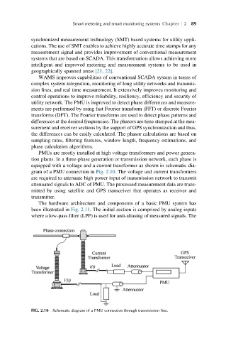
PMUs are mostly installed at high voltage transformers and power genera-
tion plants. In a three-phase generation or transmission network, each phase is
equipped with a voltage and a current transformer as shown in schematic dia-
gram of a PMU connection in Fig. 2.10. The voltage and current transformers
are required to attenuate high power input of transmission network to transmit
attenuated signals to ADC of PMU. The processed measurement data are trans-
mitted by using satellite and GPS transceiver that operates as receiver and
transmitter.
The hardware architecture and components of a basic PMU system has
been illustrated in Fig. 2.11. The initial section is comprised by analog inputs
where a low-pass filter (LPF) is used for anti-aliasing of measured signals. The
FIG. 2.10 Schematic diagram of a PMU connection through transmission line.