
Page 109 - From Smart Grid to Internet of Energy
P. 109
94 From smart grid to internet of energy
and loads. The transient power fluctuations caused by intermittent structure of
generators should be handled by an advanced monitoring system at central and
decentralized control levels at substations.
The general requirements of monitoring and troubleshooting processes of a
self-healing system are based on collecting, analyzing, diagnosing, predicting,
and prioritizing the data. The data collection enables availability of data in any
database for detailed analysis while the data analysis provides information on
asset conditions and related failure or fault risks comparing to known situations.
The identified risks are evaluated in diagnosis step to develop a self-healing
program, and verifications are performed in prediction step.
The monitoring architectures rely on data acquisition systems such as
SCADA and remote terminal units (RTUs) for condition estimations. The
acquired informations on system level of smart grid are provided by PMU
devices that ensures highly reliable and synchronized input are obtained. A
drawback of current monitoring system is related to RTUs since they do not
provide synchronized measurement and causes less accurate data acquisition.
The drawback of RTU is tackled by using GIS system to provide more accurate
localization [14]. The monitoring system is also equipped with smart sensors
and sensor nodes in field assets. In addition to data acquisition, monitoring
infrastructure generates alert signals to indicate fault or failures. The monitoring
system should provide real time and historical data for specific purposes.
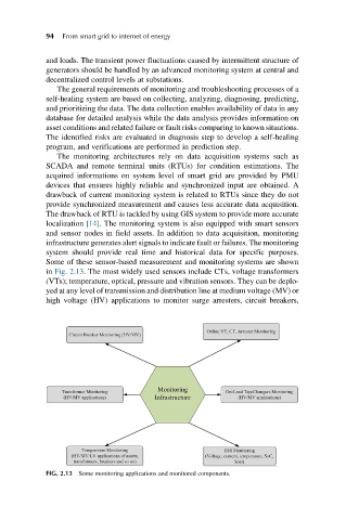
Some of these sensor-based measurement and monitoring systems are shown
in Fig. 2.13. The most widely used sensors include CTs, voltage transformers
(VTs); temperature, optical, pressure and vibration sensors. They can be deplo-
yed at any level of transmission and distribution line at medium voltage (MV) or
high voltage (HV) applications to monitor surge arresters, circuit breakers,
FIG. 2.13 Some monitoring applications and monitored components.