
Page 377 - From Smart Grid to Internet of Energy
P. 377
Roadmap from smart grid to internet of energy concept Chapter 9 341
(SMs) perform metering of electricity and energy quality at the same time. Sev-
eral efficient communication technologies such as cognitive radio (CR), power
line communication (PLC), fiber optic and cellular are recommended to
improve communication performance of EI systems. The essential intention
of the EI communication is to allow data exchange to accomplish real-time bal-
ance among energy generation rates and consumption rates.
The general EI architecture is comprised to accomplish energy routing
applications that energy routers are located at any node of EI infrastructure
as seen in Fig. 9.1. The fundamental requirement of energy router is to deploy,
manage and control the energy flow in planned and programmed operation
since it is controlled by ICT interfaces. The centralized organization of this
power network provide interconnection of several intelligent loads, DERs, stor-
age systems, customers, control and management centers. It is noted in [13] that
energy routers are proposed as a convenient interface in RES integration to
active distribution network and multi-agent systems comprise the core control-
ler of energy routers for accomplishing the control requirements. On the other
hand, the solid-state transformers (SSTs) are proposed as dynamic energy
routers due to their power handling and coordinating capabilities. The SSTs
are comprised by power converters in DC and AC operations where dynamic
energy management and power flow controls are available in ICT based con-
verter architecture. A novel energy router has been proposed in [13] that is
designed in modular structure and provides multiple operation modes including
single-phase and three-phase power interfaces, stability control features, and
distribution network capabilities.
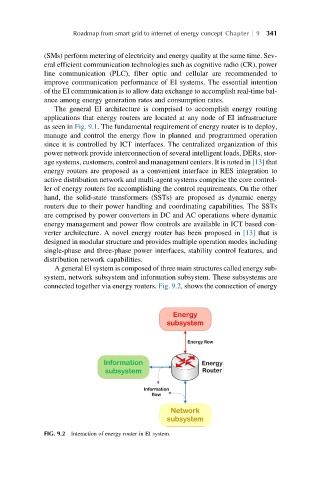
A general EI system is composed of three main structures called energy sub-
system, network subsystem and information subsystem. These subsystems are
connected together via energy routers. Fig. 9.2. shows the connection of energy
FIG. 9.2 Interaction of energy router in EI system.