
Page 89 - From Smart Grid to Internet of Energy
P. 89
Smart metering and smart monitoring systems Chapter 2 75
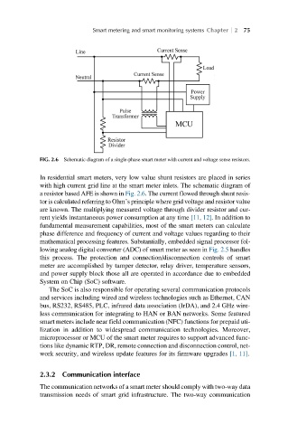
FIG. 2.6 Schematic diagram of a single-phase smart meter with current and voltage sense resistors.
In residential smart meters, very low value shunt resistors are placed in series
with high current grid line at the smart meter inlets. The schematic diagram of
a resistor based AFE is shown in Fig. 2.6. The current flowed through shunt resis-
tor is calculated referring to Ohm’s principle where grid voltage and resistor value
are known. The multiplying measured voltage through divider resistor and cur-
rent yields instantaneous power consumption at any time [11, 12]. In addition to
fundamental measurement capabilities, most of the smart meters can calculate
phase difference and frequency of current and voltage values regarding to their
mathematical processing features. Substantially, embedded signal processor fol-
lowing analog digital converter (ADC) of smart meter as seen in Fig. 2.5 handles
this process. The protection and connection/disconnection controls of smart
meter are accomplished by tamper detector, relay driver, temperature sensors,
and power supply block those all are operated in accordance due to embedded
System on Chip (SoC) software.
The SoC is also responsible for operating several communication protocols
and services including wired and wireless technologies such as Ethernet, CAN
bus, RS232, RS485, PLC, infrared data association (IrDA), and 2.4 GHz wire-
less communication for integrating to HAN or BAN networks. Some featured
smart meters include near field communication (NFC) functions for prepaid uti-
lization in addition to widespread communication technologies. Moreover,
microprocessor or MCU of the smart meter requires to support advanced func-
tions like dynamic RTP, DR, remote connection and disconnection control, net-
work security, and wireless update features for its firmware upgrades [1, 11].
2.3.2 Communication interface
The communication networks of a smart meter should comply with two-way data
transmission needs of smart grid infrastructure. The two-way communication