
Page 88 - From Smart Grid to Internet of Energy
P. 88
74 From smart grid to internet of energy
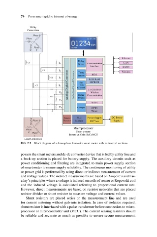
FIG. 2.5 Block diagram of a three-phase four-wire smart meter with its internal sections.
powers the smart meters and dc-dc converter device that is fed by utility line and
a back-up section is placed for battery-supply. The auxiliary circuits such as
power conditioning and filtering are integrated to main power supply section
of smart meter to ensure supply reliability. The continuous monitoring of utility
or power grid is performed by using direct or indirect measurement of current
and voltage values. The indirect measurements are based on Ampere’s and Far-
aday’s principles where a voltage is induced on coils of sensor or Rogowski coil
and the induced voltage is calculated referring to proportional current rate.
However, direct measurements are based on resistor networks that are placed
resistor divider or shunt resistor to measure voltage and current values.
Shunt resistors are placed series on the measurement line and are used
for current metering without galvanic isolation. In case of isolation required,
shunt resistor is interfaced with a pulse transformer before connection to micro-
processor or microcontroller unit (MCU). The current sensing resistors should
be reliable and accurate as much as possible to ensure secure measurement.