
Page 82 - Fundamentals of Enhanced Oil and Gas Recovery
P. 82
70 Ramin Moghadasi et al.
injection gas. This prevents the development of miscibility between injected gas
and reservoir oil, as it was about to happen through CGD. However, if these all
occurred, the process would not be very efficient. Fortunately, there is a positive
mechanism as explained in subsequent lines.
• After some periods of injection, some of the oil will be rich in light intermediates.
Thus as it contacts fresh gas, less condensation occurs. Nonetheless, the gas phase will
strip some middle intermediates from the oil. As a result, the gas phase gets rich in
both light and middle intermediates. This gas will contact the oil while stripping less
middle intermediates, still losing light intermediates. Such a combination of vaporiza-
tion/condensation continues until miscibility is developed in an efficient way.
3.2.1.2.3 Minimum Miscibility Enrichment
As discussed before, pressure would modify phase behavior and miscibility can be
obtained for a combination of solutions that were not miscible previously. However,
there is an alternative to changing pressure for miscibility to be reached. This alternative
deals with injection fluid composition alternation. For instance, in a condensing gas
process, injection fluid composition could be enriched to a minimum amount at which
the critical tie line passes through its composition. This is to be done at a fixed pressure.
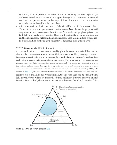
This minimum enrichment is called the minimum miscibility enrichment (MME). As
shown in Fig. 3.7, the miscibility at fixed pressure can only be obtained through enrich-
ment process to MME. In this typical example, the injection fluid will be enriched with
light intermediates, which decreases the density difference between reservoir oil and
injection fluid. Indeed, this means more similarity between the oil and injection fluid.
C 1 S = Original injected solvent composition
O = Reservoir oil composition
S
Two-phase envelope
P = P 1 MME
Critical point
O
Critical tie line
C + C –C 6
2
7
Figure 3.7 MME on ternary diagram [29].