
Page 233 - Fundamentals of Gas Shale Reservoirs
P. 233
SEISMIC PHENOMENA 213
An MEQ is defined in this article as an earthquake with
magnitude less than or equal to zero. The magnitude that
represents the measure of the size of an earthquake is
expressed as the logarithmic function of the amplitudes
of the generated seismic wave. As consequence of
the logarithmic relationship, an increase of one unit in
magnitude corresponds to 10‐fold increase in seismic
wave amplitudes. There exist different magnitude scales,
including, among others, local magnitude, M , body wave
L
magnitude, m , surface wave magnitude, M , and moment
b
S
magnitude, M . The different magnitude scales are calcu
w
lated from different seismic wave types observed at
different frequencies. For that reason, the magnitude
scales generally yield different values for the same earth
quake. Region‐specific or global conversion relations are
available, which allow magnitudes to be converted from
Y (N) one scale to another.
A seismic source (e.g., a tectonic earthquake or nuclear
X (E)
explosion) is best described mathematically by its moment
tensor. A seismic moment tensor can be expressed as a super
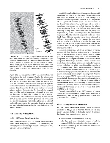
FIGURE 10.2 LEFT—Map view of a discrete fracture network position of an isotropic component, a double‐couple (DC)
(DFN) model of the Marcellus Shale formation showing the traces of component, and a compensated linear vector dipole (CLVD)
the natural fracture network on a horizontal plane at the depth of the component. The isotropic part of the seismic moment tensor
wellbore (gray) with simulated hydraulic fractures in 3D (black). results from volume change in the source region. For example,
Natural fracture reactivation was the primary mechanism of reservoir nuclear explosions and MEQs caused by sudden extension of
stimulation. RIGHT—The wellbore with only the hydraulic fractures opening‐mode fractures during fracture treatments are isotropic
from the diagram at left. See Lacazette et al. (2014) for more
discussion. sources that involve a volume increase in the source region.
A shear slip along a planar surface, the model for most earth
quakes, is adequately described by the DC component. Processes
Figure 10.2 and imagine that MEQs are generated only on known to produce CLVD components in seismic moment
the fractures that took proppant. Clearly, the microseisms tensors include the opening and closing of tensile cracks due to
will define a cloud, not a sharp, well‐defined fracture plane. fluid movements (e.g., Frohlich, 1994) and the superposition of
Also we should expect fluid leakoff into the fracture net two of more DC events that occur along faults with different
work and concomitant microseismic activity resulting from orientations (Frohlich, 1994). Non‐ double‐couple earthquake
decreased friction on the natural fractures. Indeed, passive theory and observations are reviewed by Julian et al. (1998)
seismic data showed that this fracture treatment produced and Miller et al. (1998).
seismic activity that extended far beyond the propped Tectonic tremor (Shelly et al., 2007) consists of swarms
fractures. Slip on fractures causes mismatch of asperities of low‐frequency earthquakes thought to be analogous to
and increases the hydraulic conductivity of a fracture. LPLD activity observed during hydraulic fracture treatments
Consequently, the microseismic activity in the natural (Das and Zoback, 2013a, b).
fracture system should provide pathways for production
and frac hits on adjacent wells. Indeed, frac hits on adjacent
wells did occur during the simulated fracture treatment
and simulation indicates productive contribution from the 10.3.2 Earthquake Focal Mechanisms
fracture network. 10.3.2.1 Focal Mechanism Basics Focal mechanism
solutions of MEQs are a standard deliverable for most
passive seismic studies of hydraulic fracture treatments.
10.3 SEISMIC PHENOMENA Earthquake focal mechanisms are used to:
10.3.1 MEQs and Their Magnitudes • understand the stress that caused an MEQ,
Most earthquakes result from the sudden release of stored • infer the overall stress state in the volume of rock that
elastic strain energy along fractures. The fracture may be produced MEQs having focal mechanism solutions,
formed by the slip event that produces the earthquake or may • constrain or identify the orientation of fractures that
represent a preexisting feature. generated the MEQ.