
Page 234 - Fundamentals of Gas Shale Reservoirs
P. 234
214 PASSIVE SEISMIC METHODS FOR UNCONVENTIONAL RESOURCE DEVELOPMENT
A focal mechanism solution, or simply focal mechanism, of a focal mechanism solution are often treated as approxima
is a description of the orientation (strike and dip) of the tions of the orientations of Smax, Sint, and Smin (respectively).
fault plane that slipped during an earthquake and the slip If this assumption is made, then the nodal planes of the solution
direction and slip sense of the fault and of the strain are the planes of maximum shear stress. These planes may
produced by the earthquake. The term fault plane solution seem to appear to be likely orientations for new faults to form.
is a synonym. The moment tensor of an earthquake However,
is a complete mathematical description of the earth
quake movement. The moment tensor is defined as “A • The angle between the two nodal planes is 90° so that
mathematical representation of the movement on a fault the angle between the nodal planes and the P axis is 45°.
during an earthquake, comprised of nine generalized cou • In nature the angle between conjugate fault planes in
ples, or nine sets of two vectors. The tensor depends on the most rock types is about 60°, so that the angle between
source strength and fault orientation” (U.S. Geological the fault planes and Smax is about 30°. This occurs
Survey; http://earthquake.usgs.gov/learn/glossary/). The because of internal friction in the rock.
focal mechanism solution is a subset of the moment tensor
if it represents only one component of the full moment Clearly the P and T axes cannot be equivalent to Smax and
tensor. Often, the focal mechanism solution considers Smin for newly formed faults.
only the simple DC shear component of the earthquake We define the transport plane of a fault as the plane that
source; the moment tensor includes volumetric and other contains the following:
components as well. The details of earthquake mechanics
are beyond the scope of this chapter. Thorough discus • The P and T axes of the earthquake produced by the slip
sions of moment tensors are provided by Jost and event,
Herrmann (1989) and Stein and Wysession (2002). Full • The slip line of the fault,
moment tensors are not a common deliverable for • Smax and Smin (this assumes a uniaxial stress state).
hydraulic fracture monitoring studies, although very
detailed studies may provide full moment tensors for These relationships are shown in Figure 10.6. The drawings
some MEQs. show the maximum stress axis within the transport plane of
A DC focal mechanism solution is described completely
by either: a slipping fault under uniaxial stress conditions. The angle
between Smax and the fault plane is approximately equal to
or sometimes less than 30° for newly formed faults. For
• The 3D orientation of one of the two possible fault planes older, reactivated fractures the angle is dependent on the
that produced the earthquake and the slip direction of the
hangingwall of the fault. (The hangingwall is the fault
block above the fault plane.) Only one fault plane needs
to be described because the other plane is perpendicular P T
to it and has the conjugate slip direction and slip sense. P T
• Two of the three principal strain axes, which are E C
mutually orthogonal. These are P (contractional), N F
(neutral, also called B), and T (extensional). Generally, N
the P and T axes are provided. C E
T P
Because the seismic radiation pattern of a slip event is sym
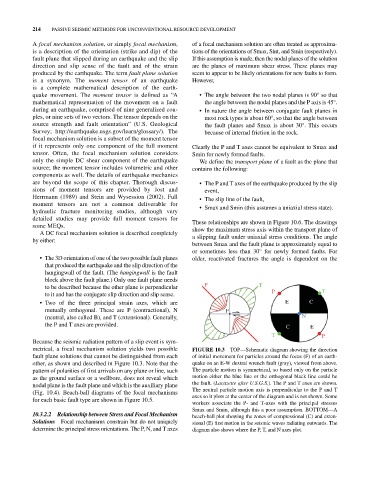
metrical, a focal mechanism solution yields two possible FIGURE 10.3 TOP—Schematic diagram showing the direction
fault plane solutions that cannot be distinguished from each of initial movement for particles around the focus (F) of an earth
other, as shown and described in Figure 10.3. Note that the quake on an E‐W dextral wrench fault (gray), viewed from above.
pattern of polarities of first arrivals on any plane or line, such The particle motion is symmetrical, so based only on the particle
as the ground surface or a wellbore, does not reveal which motion either the blue line or the orthogonal black line could be
nodal plane is the fault plane and which is the auxiliary plane the fault. (Lacazette after U.S.G.S.). The P and T axes are shown.
(Fig. 10.4). Beach‐ball diagrams of the focal mechanisms The neutral particle motion axis is perpendicular to the P and T
for each basic fault type are shown in Figure 10.5. axes so it plots at the center of the diagram and is not shown. Some
workers associate the P‐ and T‐axes with the principal stresses
Smax and Smin, although this a poor assumption. BOTTOM—A
10.3.2.2 Relationship between Stress and Focal Mechanism beach‐ball plot showing the zones of compressional (C) and exten
Solutions Focal mechanisms constrain but do not uniquely sional (E) first motion in the seismic waves radiating outwards. The
determine the principal stress orientations. The P, N, and T axes diagram also shows where the P, T, and N axes plot.