
Page 238 - Fundamentals of Gas Shale Reservoirs
P. 238
218 PASSIVE SEISMIC METHODS FOR UNCONVENTIONAL RESOURCE DEVELOPMENT
(a) Time
12:02:41 12:02:42
R1,XYZ
R2,XYZ
R3,XYZ
R4,XYZ
R5,XYZ
R6,XYZ
R7,XYZ
R8,XYZ
R9,XYZ
R10,XYZ
R11,XYZ
R12,XYZ
R13,XYZ
R14,XYZ
R15,XYZ
R16,XYZ
P S
(b) Time
1:03:30.200 1:03:30.220 1:03:30.240 1:03:30.260 1:03:30.280 1:03:30.300 1:03:30.320 1:03:30.340 1:03:30.360 1:03:30.380 1:03:30.400 1:03:30.420 1:03:30.440
R1,XYZ
R2,XYZ
R3,XYZ
R4,XYZ
R5,XYZ
R6,XYZ
R7,XYZ
R8,XYZ
R9,XYZ
R10,XYZ
R11,XYZ
R12,XYZ
R13,XYZ
R14,XYZ
R15,XYZ
R16,XYZ
P S
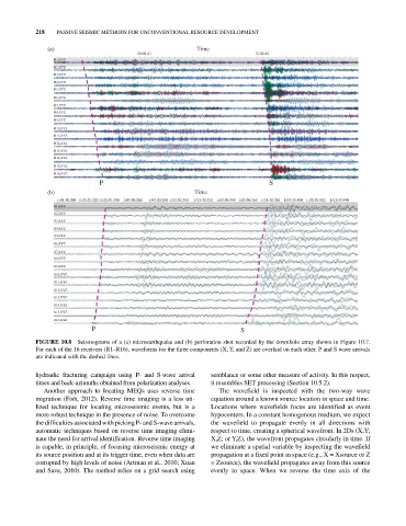
FIGURE 10.8 Seismograms of a (a) microearthquake and (b) perforation shot recorded by the downhole array shown in Figure 10.7.
For each of the 16 receivers (R1–R16), waveforms for the three components (X, Y, and Z) are overlaid on each other. P and S wave arrivals
are indicated with the dashed lines.
hydraulic fracturing campaign using P‐ and S‐wave arrival semblance or some other measure of activity. In this respect,
times and back‐azimuths obtained from polarization analyses. it resembles SET processing (Section 10.5.2).
Another approach to locating MEQs uses reverse time The wavefield is inspected with the two‐way wave
migration (Fish, 2012). Reverse time imaging is a less uti equation around a known source location in space and time.
lized technique for locating microseismic events, but is a Locations where wavefields focus are identified as event
more robust technique in the presence of noise. To overcome hypocenters. In a constant homogenous medium, we expect
the difficulties associated with picking P‐ and S‐wave arrivals, the wavefield to propagate evenly in all directions with
automatic techniques based on reverse time imaging elimi respect to time, creating a spherical wavefront. In 2Ds (X,Y;
nate the need for arrival identification. Reverse time imaging X,Z; or Y,Z), the wavefront propagates circularly in time. If
is capable, in principle, of focusing microseismic energy at we eliminate a spatial variable by inspecting the wavefield
its source position and at its trigger time, even when data are propagation at a fixed point in space (e.g., X = Xsource or Z
corrupted by high levels of noise (Artman et al., 2010; Xuan = Zsource), the wavefield propagates away from this source
and Sava, 2010). The method relies on a grid search using evenly in space. When we reverse the time axis of the