
Page 262 - Fundamentals of Light Microscopy and Electronic Imaging
P. 262
CRITERIA USED TO DEFINE VIDEO IMAGING PERFORMANCE 245
CRITERIA USED TO DEFINE VIDEO IMAGING PERFORMANCE
The imaging performance of a video camera or any electronic camera is defined in
terms of the following parameters: spatial resolution, resolution of light intensity, tem-
poral resolution, and signal-to-noise ratio. These terms were first introduced in Chapter
12. Table 13-1 lists these criteria and provides data for various electronic imaging sys-
tems including video.
Spatial Resolution
Vertical resolution is determined by the number of lines in the raster (Fig. 13-10). For
many closed-circuit TV cameras, there are up to 486 display lines. If the image of a fine
horizontal pattern of black and white stripes was always in perfect register with the
raster scanning the image, 486 alternating black and white lines could be resolved.
However, usually the match is not perfect, and the 486-line resolution is not observed.
Although 486 lines are displayed, the average vertical resolution is therefore estimated
as 0.7 486 340 lines.
With respect to horizontal resolution, the electronics are designed to resolve 800
black and white lines (400 line pairs) of a black and white square wave pattern, thus
matching the vertical resolution of 340–486 lines (Fig. 13-11). To achieve this, the
response time of the camera electronics must be fast enough to resolve signal frequen-
cies ranging from 10 MHz (400 cycles/s) down to 30 Hz (1 cycle/s). The range spanned
by these spatial frequencies defines the bandwidth of the system. At 10 MHz sampling
frequency, the response time (rise time) of the camera is very short ( 35 ns).
In tube cameras, the diameter of the scanning electron beam at the target plate is
approximately 35 m. To preserve the spatial resolution of the objective lens, the opti-
cal magnification must be sufficient to give two 35 m sampling lines (70 m) per dif-
fraction spot radius on the target plate. (The requirement for 2-fold greater sampling
frequency [raster spacing] than the spatial frequency limit in the image is related to the
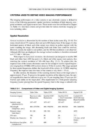
TABLE 13-1 Comparisons of Video and Digital Imaging Systems
Imaging System Video Tube Video CCD Video ICCD Digital CCD
Camera/company Newvicon video Interline CCD Interline CCD Cooled CCD
Hamamatsu Hamamatsu Gen II intensifier KAF1400 chip
Hamamatsu Roper Scientific
6
7
10
10
Intensity range 10 –10 12 10 –10 13 10 –10 11 10 –10 10
2
(photons/cm /s)
Wavelength 400–875/700 400–950/550 400–850/520 400–1100/700
(range/max. sens.)
Dynamic range 80–100 100–300 100 4095
(min./max.)
S/N ratio 180 80 80 212
Display rate (frames/s) 30 30 30 1.5 (max. at full
frame)
Resolution at face plate 470 600 600 1343
(samples/cm)