
Page 261 - Fundamentals of Light Microscopy and Electronic Imaging
P. 261
244 VIDEO MICROSCOPY
• Focus the object and adjust the offset and gain settings as described until the object
just becomes visible. This unprocessed image is called the raw image. If the image
of the object looks indistinct and has very low contrast, even after some adjustments
to the gain and offset, the raw image may appear mottled and blotchy (Fig. 13-8a).
The blotchy appearance is due to optical faults, imperfect lens surfaces, and dust
and scratches on the optics. In addition, uneven illumination can produce prominent
gradients in light intensity across the image. These are removed by background
subtraction.
• Initiate background subtraction with live frame averaging. For moving objects, a
frame average of 4–8 works well. Move the specimen laterally with the stage con-
trols to expose an adjacent blank region on the specimen slide, or if adjacent regions
contain objects or debris, defocus the microscope slightly. Upon starting background
subtraction, the averaged background image is held in memory in a frame buffer and
is subtracted from each new image frame acquired by the camera. Because the back-
ground image is subtracted from itself, the TV screen initially looks perfectly blank.
Return to focus and relocate the specimen, which should now be visible with
remarkable clarity and contrast. The image is now called a processed image.
• Make final adjustments to the contrast using the contrast menus of the digital image
processor.
• The enhanced images can be examined live on TV or videotaped or printed.
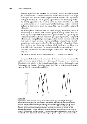
The gain and offset adjustments associated with electronic enhancement can also be
used to improve the spatial resolution in a video image. If the image of two overlapping
diffraction spots is adjusted so that the amplitude difference between the trough between
the two peaks and the peaks themselves ranges from black to white, contrast is greatly
improved (Fig. 13-9; see also Inoué, 1989).
255
Intensity
0
(a) (b)
Figure 13-9
Improvement of spatial resolution by video enhancement. (a) According to Rayleigh’s
criterion for spatial resolution, two identical overlapping diffraction spots corresponding to
two point sources of light (solid curves) can be resolved when the diffraction peak of one
spot overlies the first minimum of the other. The summation of the individual profiles is
depicted by the dotted line and represents the intensity profile seen by the eye. At this
distance of separation, the dip in intensity between the two peaks can just be perceived by
the eye. (b) Resolution can be improved in video microscopy by adjusting the offset to bring
the intensity at the dip close to 0 and readjusting the gain to bring the maxima to saturation.