
Page 258 - Fundamentals of Light Microscopy and Electronic Imaging
P. 258
ELECTRONIC CAMERA CONTROLS 241
256
= 0.333
0.5 1.0
Output signal 2.0 = 3.0
160
60
10
0
60 256
Input signal
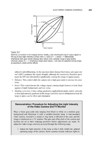
Figure 13-7
Gamma ( ) function of an imaging device. Ideally, a plot showing the log of output signal vs.
the log of input light intensity is linear with a value of 1. values 1 differentially
emphasize dark gray values (display dark values over a greater range of gray levels),
whereas values of 1 emphasize bright pixel values. can also be adjusted during image
processing to create similar effects.
subject to photobleaching. As the specimen fades during observation, auto-gain con-
trol (AGC) maintains the signal strength, although for extensively bleached speci-
mens the S/N ratio deteriorates significantly, causing the image to appear grainy.
• Enhance. This control shifts the camera into a high gain mode to increase its sensi-
tivity.
• Invert. This control inverts the voltage signal, causing bright features to look black
against a bright background, and vice versa.
• Shading correction. A bias voltage gradient is applied horizontally and/or vertically
so that light intensity gradients in the image caused by uneven illumination from the
lamp or optics can be offset and eliminated.
Demonstration: Procedure for Adjusting the Light Intensity
of the Video Camera and TV Monitor
Place a linear gray-scale strip ranging from black to white on a medium gray
background and illuminate it with a variable-intensity lamp. A lens-mounted
video camera, secured to a tripod or ring stand, is directed at the card, and the
image is displayed on a TV monitor. The gain and offset dials of the camera and
monitor are set to their midrange positions before adjustments are made. To
adjust the video image correctly, proceed through the following steps:
1. Adjust the light intensity of the lamp so that it falls within the optimal
operating range of the camera. Some cameras include indicator lights to