
Page 255 - Fundamentals of Light Microscopy and Electronic Imaging
P. 255
238 VIDEO MICROSCOPY
1
0
3
2
5
• 4
• •
•
Field 1 Field 2
•
• •
•
477
479
481 478
480
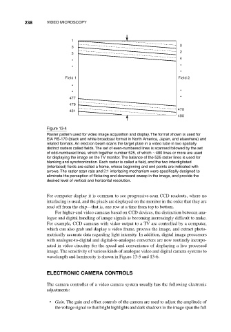
Figure 13-4
Raster pattern used for video image acquisition and display. The format shown is used for
EIA RS-170 (black and white broadcast format in North America, Japan, and elsewhere) and
related formats. An electron beam scans the target plate in a video tube in two spatially
distinct rasters called fields. The set of even-numbered lines is scanned followed by the set
of odd-numbered lines, which together number 525, of which 480 lines or more are used
for displaying the image on the TV monitor. The balance of the 525 raster lines is used for
blanking and synchronization. Each raster is called a field, and the two interdigitated
(interlaced) fields are called a frame, whose beginning and end points are indicated with
arrows. The raster scan rate and 2:1 interlacing mechanism were specifically designed to
eliminate the perception of flickering and downward sweep in the image, and provide the
desired level of vertical and horizontal resolution.
For computer display it is common to see progressive-scan CCD readouts, where no
interlacing is used, and the pixels are displayed on the monitor in the order that they are
read off from the chip—that is, one row at a time from top to bottom.
For higher-end video cameras based on CCD devices, the distinction between ana-
logue and digital handling of image signals is becoming increasingly difficult to make.
For example, CCD cameras with video output to a TV are controlled by a computer,
which can also grab and display a video frame, process the image, and extract photo-
metrically accurate data regarding light intensity. In addition, digital image processors
with analogue-to-digital and digital-to-analogue converters are now routinely incorpo-
rated in video circuitry for the speed and convenience of displaying a live processed
image. The sensitivity of various kinds of analogue video and digital camera systems to
wavelength and luminosity is shown in Figure 13-5 and 13-6.
ELECTRONIC CAMERA CONTROLS
The camera controller of a video camera system usually has the following electronic
adjustments:
• Gain. The gain and offset controls of the camera are used to adjust the amplitude of
the voltage signal so that bright highlights and dark shadows in the image span the full