
Page 254 - Fundamentals of Light Microscopy and Electronic Imaging
P. 254
TYPES OF VIDEO CAMERAS 237
Magnetic
Target deflecting coils
Cathode
Photons
Electron beam Heater
Image plane
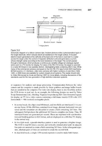
Figure 13-3
Schematic diagram of a vidicon camera tube. Incident photons strike a photosensitive layer of
the target electrode, which reduces electrical resistance in the target surface. A focused
electron beam generated at the cathode at the back end of the tube is scanned in a raster
across the target under the control of magnetic deflection coils and generates a current,
whose strength varies according to the local resistance in the target. The current passes
through a transducer, which produces a continuously variable voltage (an analogue signal)
and is sent to a TV monitor for display. For tubes of the RS-170 format, the target is scanned
in a raster 60 times/s in two spatially distinct, interdigitating fields containing 262.5 lines. While
many of the commercial cameras are based on the EIA RS-170–type format (525 lines/frame,
60 field scans/s, 2:1 interlace), video tube cameras with higher numbers of scan lines (1025,
1225, or 2000 lines) are available for custom closed-circuit systems. The reader should refer
to Video Microscopy by Inoué and Spring (1997) for more details, including discussions of the
standards used for the new generation of high-definition television systems.
or sequences for analysis and image processing. Communication between the video
camera and the computer is made possible by frame grabbers and image buffer boards
that are installed in the computer. For video rate display, there is also flexibility in how
the CCD device is read out. As an example, the following designs are used by Video
Scope International, Ltd., (Sterling, Virginia) for producing EIA video formatted signals
for display on TV for a video camera containing a full-frame transfer CCD with 1134
(horizontal) 486 (vertical) rectangular pixels.
• In normal mode, the chip is read 60 times/s, and two fields are interlaced 2:1 to cre-
ate one frame. Of the 486 lines contained in an image, alternate horizontal rows are
saved and the remainder are discarded to create a field containing 243 lines. The
subsequent field produces the additional 243 lines to complete one frame. Thus, 30
interlaced frames are generated per second. These are imprinted with synchroniza-
tion and blanking pulses in EIA format, and are displayed on a 486-line TV display
in the normal way.
• In low-light mode, a pseudo-interlace pattern is used to generate a brighter image.
The CCD is read 60 times a second, and vertically oriented pixel pairs in adjacent
line pairs are summed to create a field containing 243 lines. In the subsequent expo-
sure, alternate pairs of lines are summed to create the second field.
• In dual-field mode, a single 1/30 second exposure is used to make both frames.