
Page 252 - Fundamentals of Light Microscopy and Electronic Imaging
P. 252
CONFIGURATION OF A VIDEO CAMERA SYSTEM 235
TV monitors
Processed
Video image
camera
Digital image
processor
Thermal
Raw printer
image
Microscope VCR
Camera controller
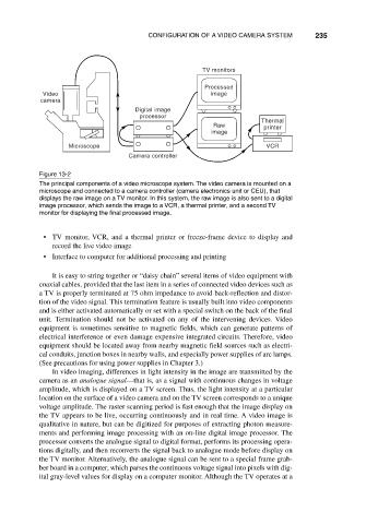
Figure 13-2
The principal components of a video microscope system. The video camera is mounted on a
microscope and connected to a camera controller (camera electronics unit or CEU), that
displays the raw image on a TV monitor. In this system, the raw image is also sent to a digital
image processor, which sends the image to a VCR, a thermal printer, and a second TV
monitor for displaying the final processed image.
• TV monitor, VCR, and a thermal printer or freeze-frame device to display and
record the live video image
• Interface to computer for additional processing and printing
It is easy to string together or “daisy chain” several items of video equipment with
coaxial cables, provided that the last item in a series of connected video devices such as
a TV is properly terminated at 75 ohm impedance to avoid back-reflection and distor-
tion of the video signal. This termination feature is usually built into video components
and is either activated automatically or set with a special switch on the back of the final
unit. Termination should not be activated on any of the intervening devices. Video
equipment is sometimes sensitive to magnetic fields, which can generate patterns of
electrical interference or even damage expensive integrated circuits. Therefore, video
equipment should be located away from nearby magnetic field sources such as electri-
cal conduits, junction boxes in nearby walls, and especially power supplies of arc lamps.
(See precautions for using power supplies in Chapter 3.)
In video imaging, differences in light intensity in the image are transmitted by the
camera as an analogue signal—that is, as a signal with continuous changes in voltage
amplitude, which is displayed on a TV screen. Thus, the light intensity at a particular
location on the surface of a video camera and on the TV screen corresponds to a unique
voltage amplitude. The raster scanning period is fast enough that the image display on
the TV appears to be live, occurring continuously and in real time. A video image is
qualitative in nature, but can be digitized for purposes of extracting photon measure-
ments and performing image processing with an on-line digital image processor. The
processor converts the analogue signal to digital format, performs its processing opera-
tions digitally, and then reconverts the signal back to analogue mode before display on
the TV monitor. Alternatively, the analogue signal can be sent to a special frame grab-
ber board in a computer, which parses the continuous voltage signal into pixels with dig-
ital gray-level values for display on a computer monitor. Although the TV operates at a