
Page 308 - Fundamentals of Light Microscopy and Electronic Imaging
P. 308
FLAT-FIELD CORRECTION 291
Raw image
I R Intensity Dark level
Pixel number
Flat field
Shading Shading error
error
I F Intensity Dark level
Pixel number
Dark image
Intensity Dark level
I
D
Pixel number
I = Corrected image = (I – I ) / (I – I )
C
R
D
F
D
Corrected image
I C Intensity
Pixel number
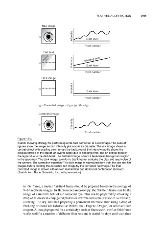
Figure 15-4
Sketch showing strategy for performing a flat-field correction of a raw image. The pairs of
figures show the image and an intensity plot across its diameter. The raw image shows a
central object with shading error across the background; the intensity profile shows the
irregular profile of the object, an overall slope due to shading error, and an overall boost in
the signal due to the dark level. The flat-field image is from a featureless background region
in the specimen. The dark image, a uniform, blank frame, contains the bias and read noise of
the camera. The correction equation: The dark image is subtracted from both the raw and flat
images before dividing the corrected raw image by the corrected flat image. The final
corrected image is shown with uneven illumination and dark-level contribution removed.
(Sketch from Roper Scientific, Inc., with permission)
in this frame, a master flat-field frame should be prepared based on the average of
9–16 replicate images. In fluorescence microscopy, the flat-field frame can be the
image of a uniform field of a fluorescent dye. This can be prepared by streaking a
drop of fluorescein-conjugated protein or dextran across the surface of a coverslip,
allowing it to dry, and then preparing a permanent reference slide using a drop of
ProLong or SlowFade (Molecular Probes, Inc., Eugene, Oregon) or other antifade
reagent. Although prepared for a certain dye such as fluorescein, the flat-field frame
works well for a number of different filter sets and is useful for days until such time