
Page 311 - Fundamentals of Light Microscopy and Electronic Imaging
P. 311
294 DIGITAL IMAGE PROCESSING
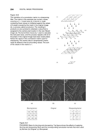
Figure 15-6
–1 –1 –1
The operation of a convolution matrix in a sharpening (a)
–1 9 –1
filter. The matrix in this example has numeric values
–1 –1 –1
covering a 3 3 pixel area (a). A kernel or mask
containing these values is multiplied against the values
of 9 pixels covered by the mask in the original image
(b), a process called convolution. The resulting 9
products (c) are summed to obtained a value that is
assigned to the central pixel location in the new filtered 61 68 100 110 125
image (d). The kernel then moves by 1 pixel to calculate (b) 65 72 95 118 119
the next pixel value, and the process repeats until all of 60 73 100 120 130
the pixels in the original image have been recalculated. 68 77 103 115 124
Notice the values in the convolution matrix used for 66 67 98 114 114
sharpening. The central value is emphasized (matrix
value 9) relative to the 8 surrounding values. The sum
of the values in the matrix is 1.
–72 –95 –118
(c)
–73 900 –120
–77 –103 –115
(d) 127
(a) (b) (c)
Blurring kernel Original Sharpening kernel
1/9 1/9 1/9 –1 –1 –1
1/9 1/9 1/9 –1 9 –1
1/9 1/9 1/9 –1 –1 –1
Figure 15-7
Convolution filters for blurring and sharpening. The figure shows the effects of applying
blurring and sharpening filters and the corresponding convolution kernels that were used.
(a) Blurred. (b) Original. (c) Sharpened.