
Page 216 - Fundamentals of Magnetic Thermonuclear Reactor Design
P. 216
198 Fundamentals of Magnetic Thermonuclear Reactor Design
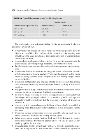
TABLE 6.4 Typical Thermal-Vacuum Conditioning Modes
Heating modes
o
Limit of residual pressure (Pa) Temperature ( C) Duration (h)
−5
10 to 10 −6 120–150 2–5
−6
10 to 10 −7 150– 300 10–50
10 and lower ∼400 50–150
−8
The design principles and serviceability criteria for sectionalised all-metal
assemblies are as follows:
l Connections with as high an elastic energy as practically possible have the
highest serviceability. The resultant of the elastic forces in a sealing zone
should have the same direction as the typical direction of contact pieces’
thermal deformation.
l A general physical serviceability criterion for a specific connection is the
elasticoplastic deforming energy needed to seal up the connection.
l Profiled connectors meet the size and metal consumption minimisation cri-
teria.
l Connectors that can accumulate the energy of elastic deformation are suit-
able for exposure to thermal cyclicity. Therefore, fasteners of highly elastic
materials, spring washers, elastic compensators, two-bearing flanges, and so
on, are called for.
l Connector configuration and material should be chosen such that mutual
deformation of connecting parts exposed to thermal cyclicity is as small as
possible.
l Equipment for heating a structure that uses detachable connections should
generate a uniform temperature field in the contact zone.
l To achieve a tight seal along the whole sealing contour, the spacing between
fastenings and flange rigidity should be as small as possible. A long-lived
connector should be sized such that the creep and relaxation of stresses are
factored in.
l Any mechanical contacts between a shell and a flange should be avoided in
the sealing zone. This is achieved through the use of slip-on flanges, clamps,
and so on.
l Connector surface conditioning processes should be chosen such that no
marks (scratches) normal to the sealing contour appear.
l When using plastic sealant (indium, lead, etc.), it is desirable to employ
separation pad radial deformation limiters or see to it that the pads are par-
ticularly rigid in the seal plane.
l Contact pieces’ profiles are not really critical to correctly designed connec-
tions that are up to 40–50 mm across. For sizable connections, symmetric