
Page 212 - Fundamentals of Magnetic Thermonuclear Reactor Design
P. 212
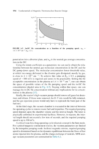
194     Fundamentals of Magnetic Thermonuclear Reactor Design


            FIGURE 6.5  In-DC He concentration as a function of the pumping speed.  n He   =
                     −3
                  13
            1.4 × 10  cm ; τ He  = 2 s.

              penetration into a divertor plate, and n  is the neutral gas average concentra-
                                            dj
            tion in the DC.
               Using the return coefficient as a parameter, we can easily obtain the rela-
            tionship between the neutral gas molecular concentration in the DC and the
            DC pump-down speed. The molecular concentration lower threshold value,
            at which ion energy delivered to the divertor gets dissipated, mostly by gas,
                            13
            is close to 2 × 10  cm  −3 . To achieve this value at R  = 0.5, a pumping
                                                           dv
                           3
            speed of ∼500 m /s is required and seems to be practicable. Setting the He
                                                            −3
                                                        13
            acceptable concentration in the plasma at 1.4 × 10   cm , one can obtain
            the space of possible values of the He pumping speed and the in-DC He
            concentration (shaded area in Fig. 6.5). Staying within that space, one can
            manage the in-DC He concentration without any implications for its concen-
            tration in the plasma [13].
               Ideally, the reactor’s high-vacuum pumps should remove all gases but deute-
            rium and tritium. If those were removed, the D–T mix would be fully returned,
            and the gas injection system would only have to replenish the burnt part of the
            fuel mix.
               At the third stage, the vacuum chamber is evacuated in the interval between
            the operating cycles to remove waste fuel and impurities. The required pumping
            speed depends upon the chamber volume and the interval length. The latter is
            practically unlimited in experimental facilities. However, in reactors, the inter-
            val length should not exceed a few tens of seconds, and the required pumping
                             3
            speed is up to 100 m /s.
               A critical issue for a long operating cycle tokamak concept is the burn mode.
            For a pulsed magnetic-confinement reactor, the vacuum parameters are limited
            by the interpulse pumping mode. In direct magnetic mirrors, required pumping
            speed is determined based on the dynamic equilibrium between the flows of fast
            atoms injected into the plasma, and the charge exchange of neutrals. MFR aver-
            age vacuum parameters are summarised in Table 6.2.