
Page 214 - Fundamentals of Magnetic Thermonuclear Reactor Design
P. 214
196 Fundamentals of Magnetic Thermonuclear Reactor Design
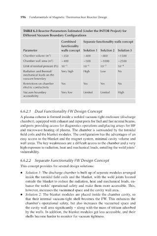
TABLE 6.3 Reactor Parameters Estimated (Under the INTOR Project) for
Different Vacuum Boundary Configurations
Combined Separate functionality walls concept
functionality
Parameter walls concept Solution 1 Solution 2 Solution 3
Chamber volume (m ) ∼350 ∼400 ∼800 ∼1500
3
2
Chamber wall area (m ) ∼400 ∼500 ∼1000 ∼2500
Limit of residual pressure (Pa) 10 −6 10 −6 10 −5 10 −4
Radiation and thermal/ Very high High Low No
mechanical loads on the
vacuum boundary
Restrictions on chamber Yes Yes Yes No
electric conductivity
Vacuum boundary Very low Limited Limited High
accessibility
6.6.2.1 Dual Functionality FW Design Concept
A plasma column is formed inside a welded vacuum-tight enclosure (discharge
chamber), equipped with exhaust and input ports for fuel and fast neutral beams,
and ports providing access for diagnostics operations and placing arrays for HF
and microwave heating of plasma. The chamber is surrounded by the toroidal
field coils and the blanket modules. The configuration has the advantages of an
easy access to the blanket and the magnet system, minimal cavity volume and
wall areas. The key weaknesses are a difficult access to the chamber and a very
high exposure to radiation, heat and mechanical loads, entailing the weld joints’
vulnerability.
6.6.2.2 Separate Functionality FW Design Concept
This concept provides for several design solutions:
l Solution 1: The discharge chamber is built up of separate modules arranged
inside the toroidal field coils and the blanket, with the weld joints located
outside the blanket to reduce the radiation, heat and mechanical loads, en-
hance the welds’ operational safety and make them more accessible. This,
however, increases the vacuumed space and the cavity wall area.
l Solution 2: The blanket modules are placed inside the chamber cavity, so
that their internal vacuum-tight shell becomes the FW. This enhances the
chamber’s operational safety, but also increases the vacuumed space and
the cavity wall area significantly – along with the mass of tritium adsorbed
by the walls. In addition, the blanket modules get less accessible, and their
shells become harder to monitor for vacuum tightness.