
Page 213 - Fundamentals of Magnetic Thermonuclear Reactor Design
P. 213
Vacuum and Tritium System Chapter | 6 195
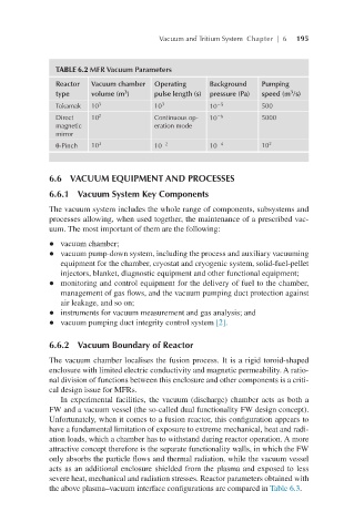
TABLE 6.2 MFR Vacuum Parameters
Reactor Vacuum chamber Operating Background Pumping
3
3
type volume (m ) pulse length (s) pressure (Pa) speed (m /s)
Tokamak 10 3 10 3 10 −5 500
Direct 10 2 Continuous op- 10 −6 5000
magnetic eration mode
mirror
θ-Pinch 10 3 10 −2 10 −4 10 2
6.6 VACUUM EQUIPMENT AND PROCESSES
6.6.1 Vacuum System Key Components
The vacuum system includes the whole range of components, subsystems and
processes allowing, when used together, the maintenance of a prescribed vac-
uum. The most important of them are the following:
l vacuum chamber;
l vacuum pump-down system, including the process and auxiliary vacuuming
equipment for the chamber, cryostat and cryogenic system, solid-fuel-pellet
injectors, blanket, diagnostic equipment and other functional equipment;
l monitoring and control equipment for the delivery of fuel to the chamber,
management of gas flows, and the vacuum pumping duct protection against
air leakage, and so on;
l instruments for vacuum measurement and gas analysis; and
l vacuum pumping duct integrity control system [2].
6.6.2 Vacuum Boundary of Reactor
The vacuum chamber localises the fusion process. It is a rigid toroid-shaped
enclosure with limited electric conductivity and magnetic permeability. A ratio-
nal division of functions between this enclosure and other components is a criti-
cal design issue for MFRs.
In experimental facilities, the vacuum (discharge) chamber acts as both a
FW and a vacuum vessel (the so-called dual functionality FW design concept).
Unfortunately, when it comes to a fusion reactor, this configuration appears to
have a fundamental limitation of exposure to extreme mechanical, heat and radi-
ation loads, which a chamber has to withstand during reactor operation. A more
attractive concept therefore is the separate functionality walls, in which the FW
only absorbs the particle flows and thermal radiation, while the vacuum vessel
acts as an additional enclosure shielded from the plasma and exposed to less
severe heat, mechanical and radiation stresses. Reactor parameters obtained with
the above plasma–vacuum interface configurations are compared in Table 6.3.