
Page 210 - Fundamentals of Magnetic Thermonuclear Reactor Design
P. 210
192 Fundamentals of Magnetic Thermonuclear Reactor Design
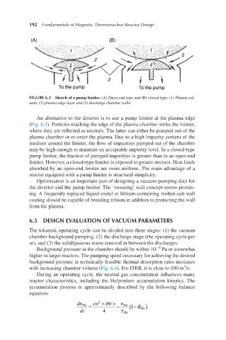
FIGURE 6.3 Sketch of a pump limiter. (A) Open-end type and (B) closed type. (1) Plasma col-
umn, (2) plasma edge layer and (3) discharge chamber walls.
An alternative to the divertor is to use a pump limiter at the plasma edge
(Fig. 6.3). Particles reaching the edge of the plasma chamber strike the limiter,
where they are reflected as neutrals. The latter can either be pumped out of the
plasma chamber or re-enter the plasma. Due to a high impurity content of the
medium around the limiter, the flow of impurities pumped out of the chamber
may be high enough to maintain an acceptable impurity level. In a closed-type
pump limiter, the fraction of pumped impurities is greater than in an open-end
limiter. However, a closed-type limiter is exposed to greater stresses. Heat loads
absorbed by an open-end limiter are more uniform. The main advantage of a
reactor equipped with a pump limiter is structural simplicity.
Optimisation is an important part of designing a vacuum pumping duct for
the divertor and the pump limiter. The ‘sweating’ wall concept seems promis-
ing. A frequently replaced liquid–metal or lithium-containing molten-salt wall
coating should be capable of breeding tritium in addition to protecting the wall
from the plasma.
6.5 DESIGN EVALUATION OF VACUUM PARAMETERS
The tokamak operating cycle can be divided into three stages: (1) the vacuum
chamber background pumping, (2) the discharge stage (the operating cycle per
se), and (3) the solid/gaseous waste removal in between the discharges.
−5
Background pressure in the chamber should be within 10 Pa or somewhat
higher in larger reactors. The pumping speed necessary for achieving the desired
background pressure at technically feasible thermal desorption rates increases
3
with increasing chamber volume (Fig. 6.4). For ITER, it is close to 100 m /s.
During an operating cycle, the neutral gas concentration influences many
reactor characteristics, including the He/protium accumulation kinetics. The
accumulation process is approximately described by the following balance
equation:
dn He = cn 2 < συ > n He ( − R1 )
−
2
dnHedt=cn <σ>4−nHeτHe1−RHe. dt 4 τ He He