
Page 209 - Fundamentals of Magnetic Thermonuclear Reactor Design
P. 209
Vacuum and Tritium System Chapter | 6 191
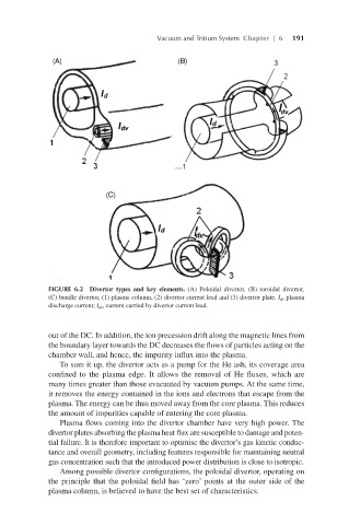
FIGURE 6.2 Divertor types and key elements. (A) Poloidal divertor, (B) toroidal divertor,
(C) bundle divertor, (1) plasma column, (2) divertor current lead and (3) divertor plate. I d , plasma
discharge current; I dv , current carried by divertor current lead.
out of the DC. In addition, the ion precession drift along the magnetic lines from
the boundary layer towards the DC decreases the flows of particles acting on the
chamber wall, and hence, the impurity influx into the plasma.
To sum it up, the divertor acts as a pump for the He ash, its coverage area
confined to the plasma edge. It allows the removal of He fluxes, which are
many times greater than those evacuated by vacuum pumps. At the same time,
it removes the energy contained in the ions and electrons that escape from the
plasma. The energy can be thus moved away from the core plasma. This reduces
the amount of impurities capable of entering the core plasma.
Plasma flows coming into the divertor chamber have very high power. The
divertor plates absorbing the plasma heat flux are susceptible to damage and poten-
tial failure. It is therefore important to optimise the divertor’s gas kinetic conduc-
tance and overall geometry, including features responsible for maintaining neutral
gas concentration such that the introduced power distribution is close to isotropic.
Among possible divertor configurations, the poloidal divertor, operating on
the principle that the poloidal field has ‘zero’ points at the outer side of the
plasma column, is believed to have the best set of characteristics.