
Page 208 - Fundamentals of Magnetic Thermonuclear Reactor Design
P. 208
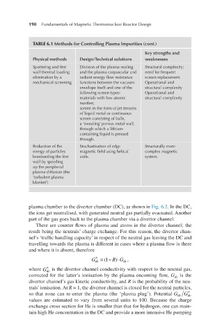
190     Fundamentals of Magnetic Thermonuclear Reactor Design


              TABLE 6.1 Methods for Controlling Plasma Impurities (cont.)
                                                         Key strengths and
              Physical methods  Design/Technical solutions  weaknesses
              Sputtering and first   Division of the plasma sealing   Structural complexity;
              wall thermal loading   and the plasma corpuscular and   need for frequent
              elimination by a   radiant energy flow resistance   screen replacement.
              mechanical screening  functions between the vacuum   Operational and
                                envelope itself and one of the   structural complexity
                                following screen types:  Operational and
                                materials with low atomic   structural complexity
                                number,
                                screen in the form of jet streams
                                of liquid metal or continuous
                                screen consisting of balls,
                                a ‘sweating’ porous metal wall,
                                through which a lithium-
                                containing liquid is pressed
                                through.
              Reduction of the   Stochastisation of edge   Structurally more
              energy of particles   magnetic field using helical   complex magnetic
              bombarding the first   coils.              system.
              wall by speeding
              up the peripheral
              plasma diffusion (the
              ‘turbulent plasma
              blanket’)


            plasma chamber to the divertor chamber (DC), as shown in Fig. 6.2. In the DC,
            the ions get neutralised, with generated neutral gas partially evacuated. Another
            part of the gas goes back to the plasma chamber via a divertor channel.
               There are counter flows of plasma and atoms in the divertor channel; the
            result being the neutrals’ charge exchange. For this reason, the divertor chan-
            nel’s ‘traffic handling capacity’ in respect of the neutral gas leaving the DC and
            travelling towards the plasma is different in cases where a plasma flow is there
            and where it is absent, therefore
                                      *
                                               ⋅
                                              )
 Gdc*=(1−R)⋅Gdc,                     G dc  = (1 − R G ,
                                                 dc
                   *
 Gdc*       where G  is the divertor channel conductivity with respect to the neutral gas,
                   dc
            corrected for the latter’s ionisation by the plasma oncoming flow, G  is the
                                                                     dc
            divertor channel’s gas kinetic conductivity, and R is the probability of the neu-
            trals’ ionisation. At R = 1, the divertor channel is closed for the neutral particles,
                                                                          *
 Gdc/Gdc*   so that none can re-enter the plasma (the ‘plasma plug’). Potential G dc  G
                                                                          dc
            values are estimated to vary from several units to 100. Because the charge
            exchange cross section for He is smaller than that for hydrogen, one can main-
            tain high He concentration in the DC and provide a more intensive He pumping