
Page 221 - Fundamentals of Magnetic Thermonuclear Reactor Design
P. 221
Vacuum and Tritium System Chapter | 6 203
High-vacuum pumping devices are placed as close to the MFR active zone
as possible, shielding the cryopanels from the plasma radiation. Heat release
in a shielded cryopanel is mostly determined by the γ-radiation. The following
data give the idea of the cryovacuum systems’ characteristics. JET, which is
currently the world’s largest tokamak, uses 16 cryogenic pumps to provide a
3
hydrogen pumping speed of 26 m /s, with an in-chamber background pressure
−8
of 10 Pa, liquid He temperature within the cryogenic area of 2.5 K, and total
cold generation and liquid He consumption of 13 W and 23 L/h, respectively
3
(5.4 kW and 0.12 m /h, respectively, for liquid nitrogen). By the regeneration
3
3
time (coming after 1000 discharges), each pump has 10 m ·Pa of H isotope,
corresponding to a 0.05 mm condensate layer. Regeneration is performed by
turbomolecular pumping [5].
The pumping of fast-atom injectors is achieved by 48 submerged pumps
3
operating with a pumping specific speed of 100 m /s, and 24 circulation pumps
3
with a pumping specific speed of 50 m /s each. The injectors have an average
−4
operating pressure of 10 Pa. Helium temperature on the cryopanel system is
close to 4 K, at which the total cold generation and liquid He consumption are
94 W and 130 L/h, respectively. By the regeneration time, each pump has up to
4
3
10 m Pa of condensate.
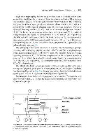
The ITER ultra-high vacuum pumping system operates on the same engi-
neering and physical principles. It is comprised of six cryosorption modules
(see functional layout in Fig. 6.6) located in divertor ducts (of which four are
pumping and two are in regeneration during normal operation).
Regeneration is an independent process in each module. The cryostat and
other reactor systems, as well as the diagnostic equipment, are pumped by tur-
bomolecular pumps.
FIGURE 6.6 ITER integral pumping module flow diagram. (1) Duct, (2) pump casing (450 K),
(3) breechblock poppet, (4) thermal shield (80 K), (5) breechblock drive, (6) cryosorption panel
(5 K), (7) safety valve.